Trailer Wiring Diagram
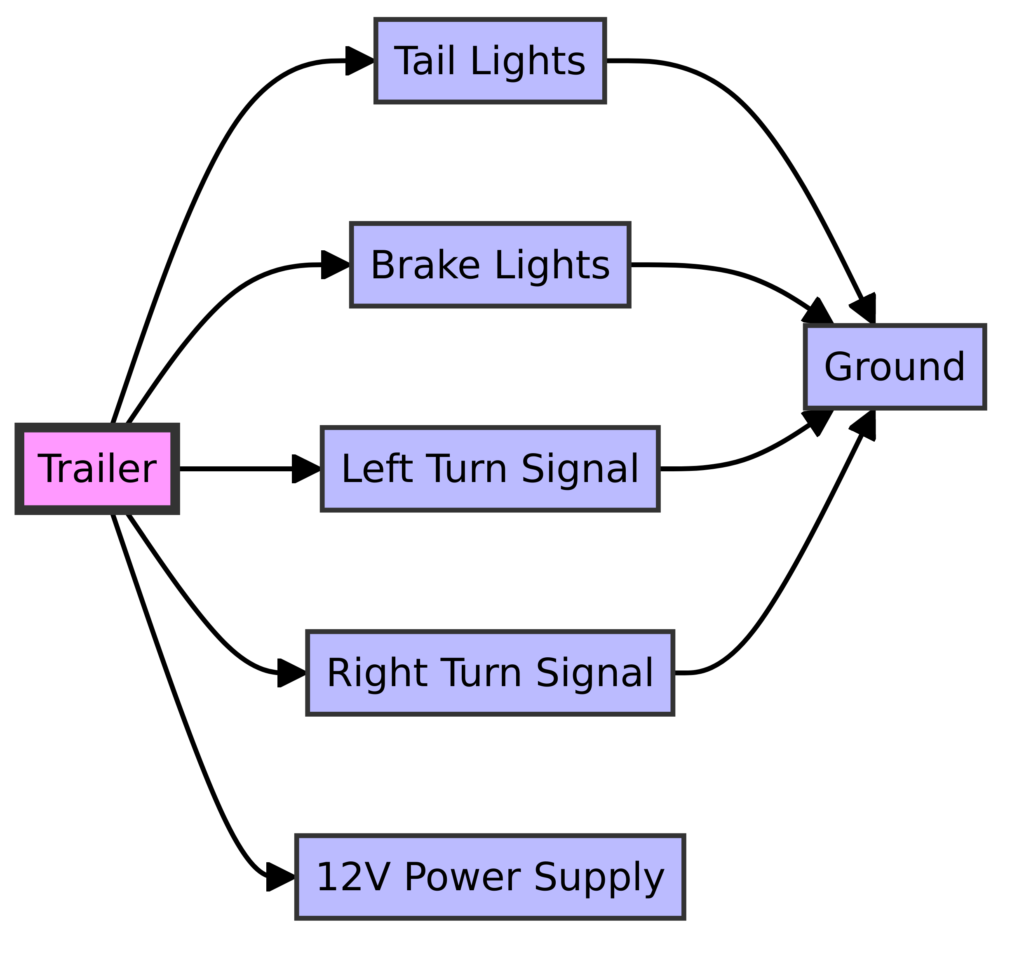
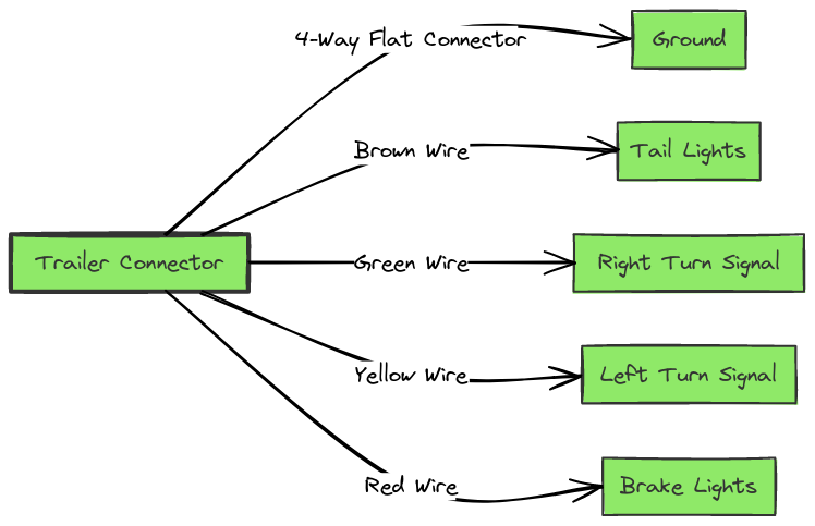
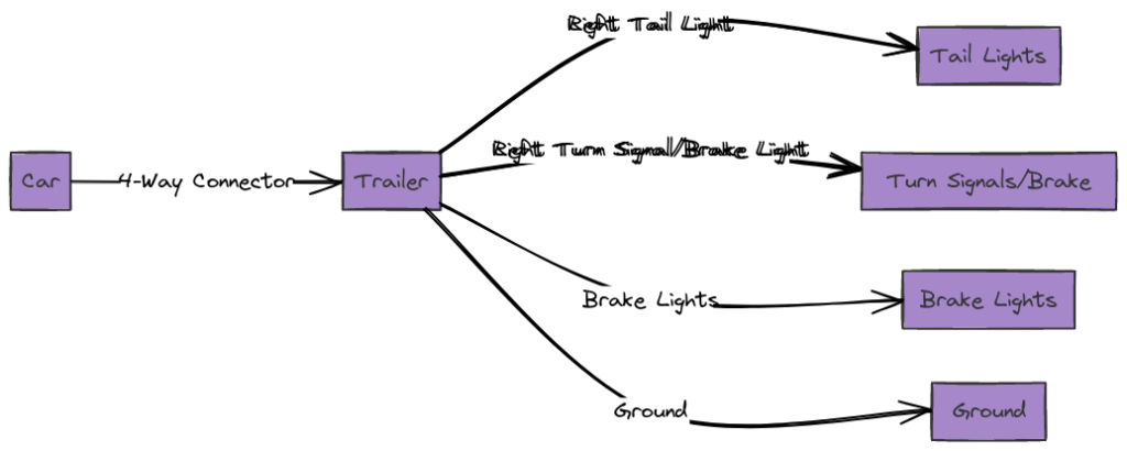
Having proper trailer lights that function correctly is a critical safety element when towing a trailer. Trailer wiring diagrams provide a map of the wiring system to help install and troubleshoot connections. Learning how to read these schematics is key to keeping your trailer operational and road-safe.
Trailer Wiring Diagrams
Diagram 1:

Diagram 2:

Diagram 3:

Diagram 4:

Diagram 5:

What’s Included in a Trailer Wiring Diagram?
Trailer wiring diagrams include a few key elements:
- The locations of the vehicle connector and trailer connector
- Wire gauge information
- Color coding for each circuit
- Details on specific functions (turn signals, brake lights, etc.)
- Ground wire locations
- Extra wiring for auxiliary functions
How to Read the Diagram?
Trailer wiring diagrams use standard symbols and layouts. Here are some tips for deciphering them:
- Wires are represented by lines
- The vehicle connector is shown on the left
- The trailer connector is on the right
- Wire colors are called out on each line
- Functions are labeled on each wire
- Arrows indicate signal directionality
- Ground wires are marked with “GND”
Following the routing and color coding makes it easier to match real-world wires during installation and repairs.
Final Thoughts
Learning to read and reference trailer wiring diagrams is an essential skill for proper functioning trailer lights. They provide a handy map of all connections and makes installation more straightforward. With the wiring details in hand, any necessary troubleshooting also becomes easier. Equipping yourself with the knowledge of how to decipher these diagrams leads to safer trailering.
