Turn Signal Wiring Diagrams
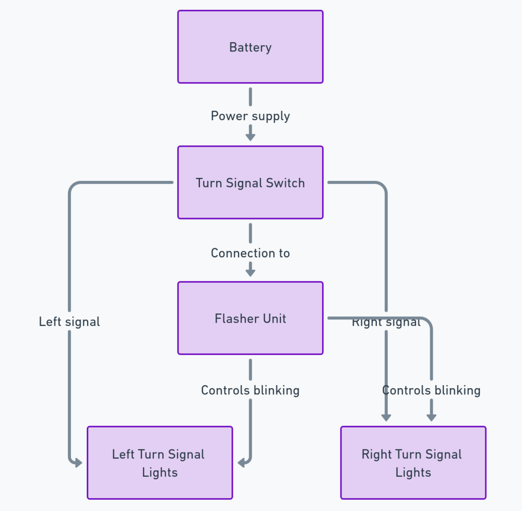
A turn signal wiring diagram is a schematic representation of the electrical circuits responsible for the operation of a vehicle’s turn signals. This diagram provides a clear visual guide to the various components, their connections, and the flow of electrical current that enables the turn signals to function properly. Understanding this diagram is crucial for troubleshooting, repair, and maintenance of a vehicle’s turn signal system.
What’s Included in a Turn Signal Wiring Diagram?
A typical turn signal wiring diagram will include the following key components:
- Turn signal switch: This is the primary control unit that the driver uses to activate the turn signals.
- Turn signal flasher: This component regulates the blinking pattern of the turn signals.
- Turn signal lamps: These are the actual lights that blink on the front and rear of the vehicle to indicate the direction of the turn.
- Wiring harness: The interconnected network of wires that transmit the electrical signals from the switch to the flasher and then to the turn signal lamps.
- Fuses and relays: These provide circuit protection and power distribution to the turn signal system.
Turn Signal Wiring Diagrams
Diagram 1:

Diagram 2:

Diagram 3:

How to Read a Turn Signal Wiring Diagram
Reading a turn signal wiring diagram requires a basic understanding of electrical circuits and the flow of electrical current. Here’s a step-by-step guide:
- Identify the key components: Locate the turn signal switch, flasher, lamps, and wiring harness on the diagram.
- Trace the circuit: Follow the path of the wires from the turn signal switch to the flasher and then to the individual turn signal lamps.
- Note the wire colors: The color-coding of the wires can help you identify the specific circuits and connections.
- Understand the symbols: Look for the standard electrical symbols used in the diagram, such as switches, lamps, and connection points.
- Identify power sources and ground connections: Determine where the turn signal system is powered from and where the ground connections are located.
Troubleshooting Turn Signal Issues
By understanding the turn signal wiring diagram, you can more effectively troubleshoot any issues that may arise with the turn signal system. Common problems may include:
- Turn signals not working: Check for power and ground at the turn signal switch and flasher, as well as inspect the wiring and bulbs.
- Turn signals blinking too fast or too slow: Verify the proper operation of the turn signal flasher.
- One turn signal not working: Trace the wiring and check for any breaks or loose connections.
Additional Considerations
When working with turn signal wiring diagrams, it’s important to keep the following in mind:
- Vehicle-specific diagrams: Each make and model of vehicle will have its own unique turn signal wiring diagram, so it’s crucial to use the correct diagram for your vehicle.
- Electrical safety: Always disconnect the battery before working on any electrical systems to avoid the risk of short circuits or shocks.
- Professional assistance: For complex or difficult-to-diagnose turn signal issues, it’s recommended to seek the help of a qualified automotive technician.
By understanding the turn signal wiring diagram and following proper troubleshooting and repair procedures, you can maintain the proper functioning of your vehicle’s turn signals, ensuring safe and reliable signaling for both you and other drivers on the road.
