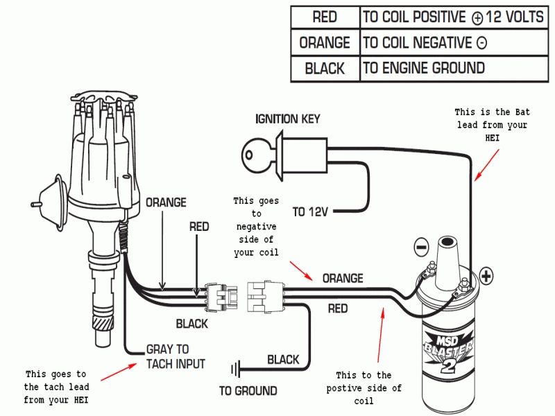
Wiring Diagram for Ignition Coil
An ignition coil is a crucial component in the combustion engine of your vehicle, responsible for providing the high-voltage spark that ignites the fuel-air mixture in the engine cylinders. Understanding the wiring diagram for an ignition coil is essential for maintaining, troubleshooting, and even replacing this important part. In this blog post, we’ll dive into the details of the ignition coil wiring diagram, helping you gain a better understanding of how this system works and how to interpret the diagram effectively.
What’s Included in the Ignition Coil Wiring Diagram?
The ignition coil wiring diagram typically includes the following components:
- Ignition Coil: The primary component that generates the high-voltage spark.
- Spark Plugs: The devices that receive the high-voltage spark and ignite the fuel-air mixture.
- Ignition Control Module (ICM) or Powertrain Control Module (PCM): The electronic control unit that manages the timing and distribution of the ignition signals.
- Battery: The power source that supplies the necessary voltage to the ignition system.
- Fuses and Relays: Protective devices that ensure the electrical system remains safe and functioning correctly.
Wiring Diagram for Ignition Coils
Diagram 1:

Diagram 2:

Diagram 3:

How to Read the Ignition Coil Wiring Diagram
Reading an ignition coil wiring diagram can seem daunting at first, but with a little practice, it becomes quite straightforward. Here’s a step-by-step guide to help you understand the diagram:
- Identify the Ignition Coil: The ignition coil is typically the central component in the diagram, and it’s important to locate it first.
- Trace the Connections: Follow the wires and connections from the ignition coil to the other components, such as the spark plugs, ICM/PCM, and the battery.
- Understand the Voltage Levels: The ignition coil requires a low-voltage input (typically 12V) from the battery, which it then transforms into a high-voltage output (around 20,000V) to the spark plugs.
- Identify the Control Signals: The ICM or PCM sends control signals to the ignition coil, determining the timing and duration of the spark.
- Recognize Fuses and Relays: Fuses and relays protect the electrical system from overloads and short circuits, and their locations are important to understand.
Troubleshooting the Ignition Coil Wiring
If you encounter issues with your vehicle’s ignition system, the wiring diagram can be a valuable tool for troubleshooting. By tracing the connections and verifying the integrity of the various components, you can often identify the root cause of the problem and take the necessary steps to address it.
Additional Considerations
While the ignition coil wiring diagram is a crucial reference, it’s important to keep in mind that the specific details may vary depending on the make, model, and year of your vehicle. Always refer to the manufacturer’s instructions or consult a professional mechanic if you’re unsure about any aspect of the ignition system.
Conclusion
The ignition coil wiring diagram is a essential tool for understanding the inner workings of your vehicle’s ignition system. By familiarizing yourself with the components, connections, and troubleshooting techniques, you can maintain your vehicle’s performance, improve its reliability, and even tackle minor repairs with confidence. Take the time to study the diagram and apply the principles we’ve discussed, and you’ll be well on your way to becoming a wiring diagram expert.
