Understanding 4 Pin Relay Wiring Diagrams for Automotive Use
Have you ever wondered what that little black box under your car’s hood does? Chances are there are a number of relays throughout your vehicle’s electrical system controlling various functions and routing power to components. Relays act like remote controlled switches, using a small electrical signal to switch a much larger current on or off.
One very common type is the 4 pin relay found in countless automotive applications. But what sets them apart from 5 pin relays? How exactly does a relay work? What do all those pins and coil diodes do? If you don’t understand relay diagrams and proper relay wiring, completing electrical repairs can quickly become frustrating.
Can you actually wire a 4 pin relay if you understand the diagram? Most definitely! We’ll cover everything you need to know, from relay basics and terminal functions to wiring instructions and troubleshooting tips. You’ll learn how to control lights, accessories, and other high current components using the right 4 pin automotive relay.
Throughout this article we’ll discuss:
- What a 4 pin relay is and how the internal components operate
- SPDT and SPST relay types and normally open/closed configurations
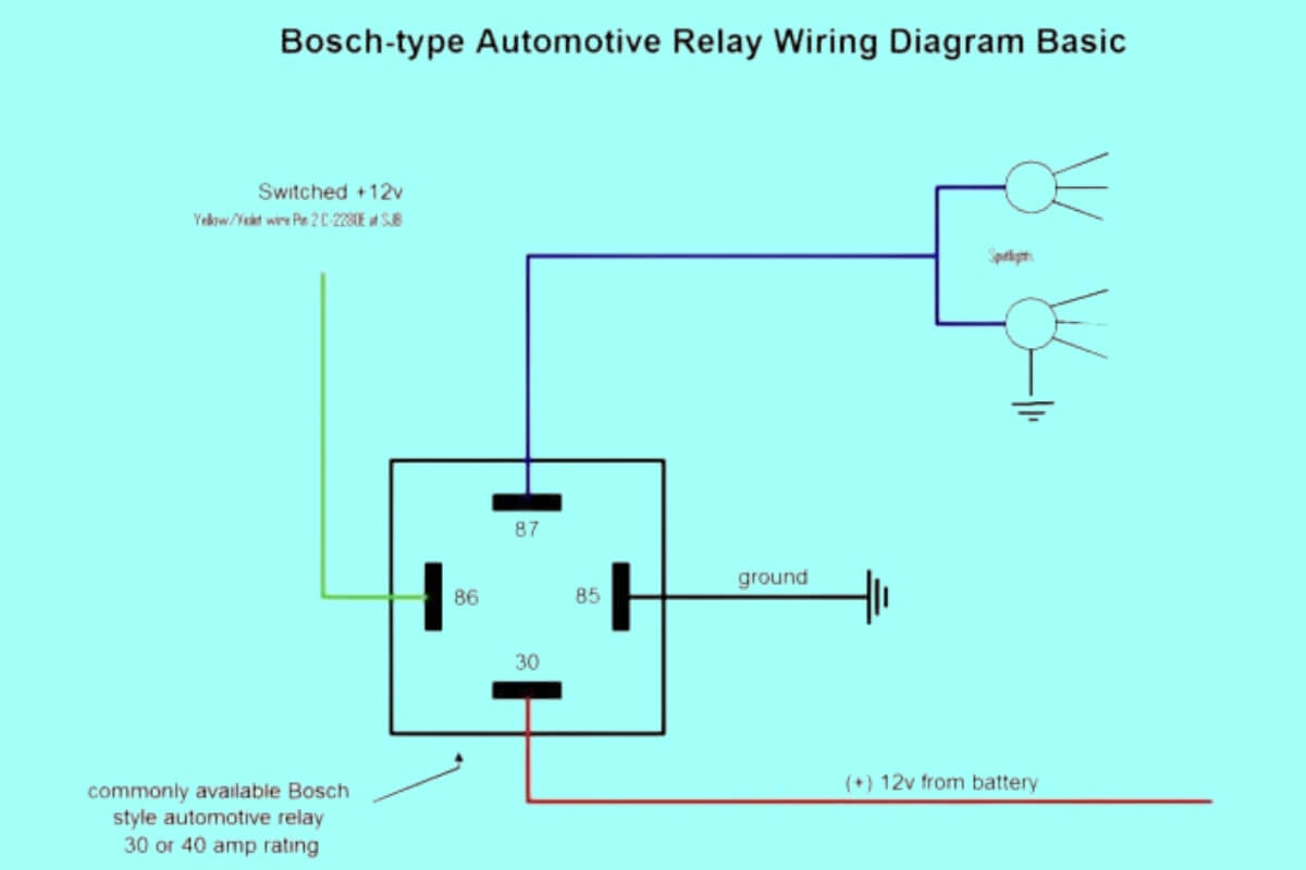
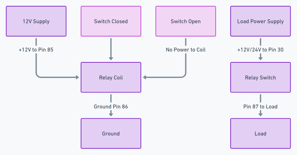
- How to interpret 4 pin relay wiring diagrams
- Steps for properly wiring a 4 pin relay to switches and loads
- Substituting 4 and 5 pin relays
- Troubleshooting bad relays and related circuits
- Specialized automotive relay designs and functions
- Safety tips and remote relay wiring considerations
Let’s start by opening up a 4 pin relay to see what’s going on inside…
What is a 4 Pin Relay and How Does it Work?
A relay is essentially a remote controlled switch with an electromagnet inside that moves the contacts. By energizing the electromagnet, known as the coil, you can flip the contacts on/off from a distance. The relay allows a low power circuit to switch functionality on another circuit that carries higher current.
4 pin relays have 4 pins emerging from a plastic casing:
- 87 – Common contact for normally open OR normally closed
- 30 – Power in for the electromagnet coil
- 87a – Normally closed contact
- 85 – Power out from electromagnet coil
Inside there are spring loaded contacts connected to pins 87 and 87a. When at rest, 87a makes contact within the relay.
The relay coil connects to pins 30 and 85. When power is applied, an magnetic field pulls the spring loaded contact away from 87a and towards 87. This breaks the connection between 87a and 87 while making contact between 87 and 30.
So by energizing the coil, you can flip the switch between the 87 and 87a contacts remotely. Pretty clever!
Now let’s compare 4 pin and 5 pin relays…
Difference Between a 4 Pin Relay and 5 Pin Relay
A 5 pin relay adds an extra 86 pin which connects to an internal diode. This additional diode is used to absorb back EMF from the collapsing magnetic field when de-energizing. This protects the switching transistor powering the relay coil.
The benefit of this diode is mainly seen in relays controlling motors, solenoids, and other inductive loads. This can increase relay lifespan and reduce electrical noise. However, 5 pin relays tend to cost more than their 4 pin counterparts.
For many basic automotive loads like lights, horns, or accessories, a 4 pin relay works just fine. You just need to account for back EMF in other ways in your circuit design. We’ll cover that later when we discuss relay wiring.
Some key differences:
- 4 pin relay = no internal diode
- 5 pin relay = internal protection diode
- 5 pin has extra 86 pin to integrate diode
- 5 pin relay has slightly longer life with inductive loads
- 4 pin relay often has lower cost
The contacts and coil operate identically otherwise between the two. And in many cases, you can actually substitute a 4 pin relay for a 5 pin with external diode or protection circuitry.
4 Pin Relay Wiring Diagrams
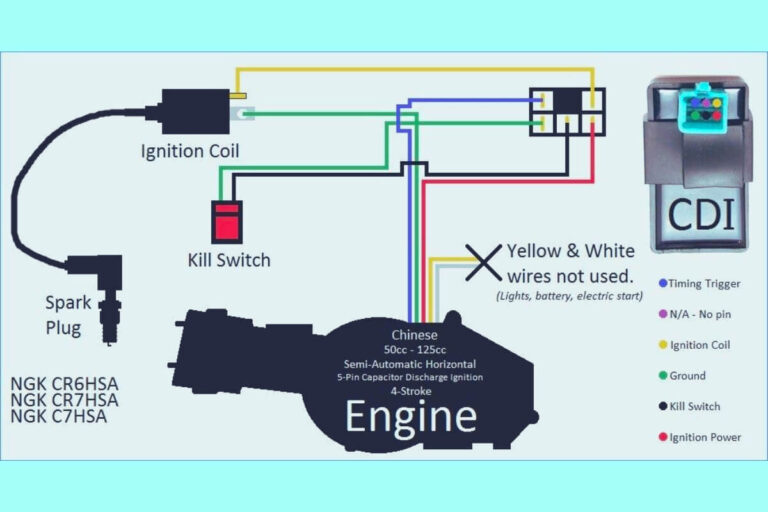
Diagram 1:

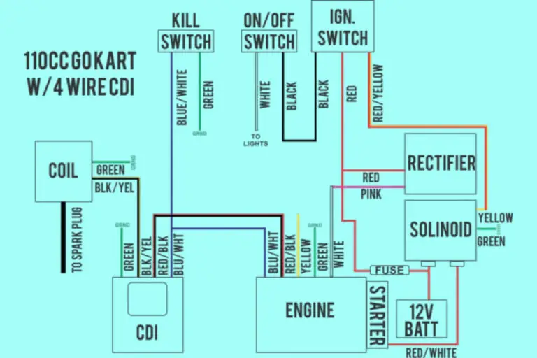
Diagram 2:

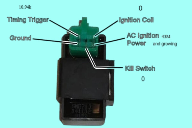
Diagram 3:

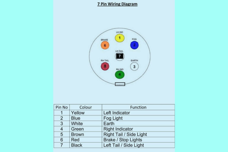
Diagram 4:

Diagram 5:
Now let’s look at common configurations…
Common 4 Pin Relay Types and Configurations
While functions vary across different automotive relays, you will typically see a few standard configurations:
SPST vs SPDT Relays
SPST stands for “Single Pole, Single Throw”. This means there is a single contact set that opens and closes. These would use the 87 and 30 pins.
SPDT means “Single Pole, Double Throw” – two contact sets which move between three terminals: one common and the other two normally opened or normally closed. This describes the typical 4 pin automotive relay with 87, 87a, and 30 pins.
Normally Open vs Normally Closed
Normally open (NO) means the contacts rest in an open state until activated. The relay connects the circuit when the coil is energized.
Normally closed (NC) has contacts resting in a closed state. Thus the circuit path is connected until the relay coil activates.
Wiring and usage depends on the load device’s default condition.
Wiring a 4 Pin Relay
Let’s walk through wiring a basic 4 pin relay for switching power to a light or other load:
Step-by-Step Wiring Instructions
- Determine load device default state and desired control logic
- Select appropriate SPST or SPDT automotive relay
- Connect pin 85 and 86 to ground
- Connect positive 12V supply voltage to pin 30
- Connect positive feed wire from control switch to pin 86
- Connect load hot wire to common pin 87
- Connect load ground wire to ground
Following this logic, the relay coil activates when switch closes, connecting voltage flow through the load. Pretty straightforward!
Using Relay for Lights, Horns, Accessories
A relay can switch power flow to a variety of automotive loads like LED light bars, horns, winches, resistors, cameras, and more. Just make sure to rate the relay properly for the expected amperage.
Use relays whenever directly powering loads from the switch is inconvenient or not feasible. Wiring harnesses keep switches in easy to reach locations like dashboards while hardware mounts out of sight.
Powering Relay Coil Correctly
Ensure proper relay and load device ratings match expected operating voltages. Use thinner gauge automotive wiring for control and signal feeds.
For the electromagnet relay coil, it takes very little current flow to energize it. Typically 150-200mA is plenty – exceeding this risks permanent activation and premature coil failure. Inrush current can briefly spike when activated to help overcome contact resistance and start initial movement.
Diode Wiring to Protect Circuit
While 4 pin relays lack internal protection diodes, you can add an external one or utilize a vehicle’s existing field collapse diode. Just connect it reverse-biased across the load or coil pins. This gives excess voltage spikes an escape route when field collapses, protecting the relay and power transistor.
Now we know the basic workings of a 4 pin relay. Let’s discuss substituting one for a 5 pin…
4 Pin Relay vs 5 Pin Relay
While similar in most respects, the key difference again lies with that internal protection diode. Since a 5 pin relay has a diode built-in, can you substitute a 4 pin?
It depends…
For most lighting, horn, or accessory loads you can safely swap them since back EMF poses little risk. Just be sure to externally diode protect any inductive loads.
However, some modern vehicles may use data communication or experience significant load changes that make relay substitution ill-advised. Manufacturers integrate 5 pin relays into a number of critical systems. Replacing them means potentially losing out on voltage regulation and load compensation features.
Always check OEM specifications when considering relay swapping. If simply restoring basic functionality however, a quality automotive 4 pin relay should perform just fine.
Let’s look at troubleshooting some problematic relay scenarios…
Troubleshooting Automotive Relay Issues
While ruggedly designed, vehicle-based relays can still fail or develop problems over years of vibration, temperature swings, moisture exposure, and overloaded circuits. Fortunately troubleshooting them is pretty straightforward.
Relay Not Switching On – Potential Causes
If your relay worked previously but fails to engage, possible culprits include:
- Broken control circuit or wiring
- Failed activation switch
- Faulty transistor or fuse feeding the relay coil
- Mechanical jamming or contact welding
- Insufficient coil current due to resistance
- Excessive load attempting activation
Using a multi-meter, you can diagnose where signal or power interruption occurs. Check control wiring continuity, switch function, coil voltage at activation, contact resistance, and load draw.
Relay Stuck On – Troubleshooting Tips
Just as problematic as non-activation is permanent activation, often indicated by a continually running load like lights or motor. Typical causes of a stuck automotive relay include:
- Contacts welded shut from overloading
- Internal diode or transistor short
- Debris keeping contacts closed
- Failed return spring mechanism
- External short/voltage spike damage
Carefully check internal relay components for visible issues. Test continuity across the load pins with coil de-energized – an open circuit indicates properly functioning contacts whereas continuity points to contact welding or shorting. Measure coil resistance as well – a low OHM reading can signal external short circuit damage.
Also inspect wiring insulation, harnesses, and upstream components for faults allowing excessive current to reach the relay.
Diagnosing Bad Relay vs Bad Circuit
How can you tell whether replacing a suspect 4 pin relay will actually remedy an electrical problem? It helps to understand surrounding components.
For example, repeated blowing of a fuse feeding a relay suggests high current seen at the load device itself. Like lights with bad grounds or motor windings shorted to the chassis. Replacing the relay alone won’t address the root problem.
However, if fuses and wiring check out okay but activation or switching fails, you likely have a bad relay. Just be judicious with troubleshooting steps before condemning it prematurely!
Automotive Relay Design Variations
We’ve covered standard 4 pin relays but you’ll encounter other configurations tailored for unique automotive applications:
Low Current Signal/High Current Load Relays
Some types handle a lower control circuit current while the switched path carries higher amperage. This allows extended switch, sensor, and electronics lifespan. It also permits smaller gauge control wiring since only the path to the coil carries a tiny load.
Latching and Non-Latching Timing Relays
Intermittent wiper, turn signals, cooling fans, and headlamps use specialized timing relays. These “latch on” to maintain function without needing to manually hold a switch or maintain coil power, typically for 5-60 seconds. This allows a momentary signal to trigger their longer cyclic operation.
Various Relay Manufacturers
Popular automotive relay brand names include Bosch, Tyco, Omron, Finder, Leach, Potter & Brumfield, and TE Connectivity – among many others. While differing aesthetically, internal workings and termination layouts align closely between makes.
Now let’s examine some best practices when wiring automotive relays…
Safety Considerations for Automotive Relays
Despite their simplicity, observing some basic guidelines ensures safe relay functionality:
Properly Rating and Sizing Relay
Choose a relay that exceeds expected load current to prevent overheating contacts and potential meltdown under heavy loads. Consider voltage capacity as well – some automotive types handle 12V vehicles, others for 24V trucks or equipment.
Avoiding Unintended Activation
Carefully rout wiring so loose harness strands don’t inadvertently make contact across terminals. This could engage the relay unexpectedly. Also isolate control switches to prevent accidental activation.
Preventing Overheating + Contact Issues
When functioning properly, relays output very little heat themselves. But insufficient wiring gauge or loose terminations can allow excessive current flow through circuits. This heats contacts and leads to early failure.
Critical Usage Considerations
Avoid using relays beyond automakers’ intended purpose and safety margin limits. Components like airbags, brake anti-lock motor controls, stability programs, and charging systems often use micro-controller relays not intended for substitution or secondary usages without thorough understanding of the complex programming and algorithms involved.
Adhering to these guidelines helps ensure long service life from automotive relays keeping your car’s vital functions and accessories operating properly over thousands of miles!
Other 4 Pin Relay Applications
Beyond automotive uses, you’ll find basic SPST and SPDT 4 pin relays in a variety of applications:
- HVAC systems utilize timing and switching relays for heat pumps, auxiliary heat, circulation fans, compressors, valves, and dampers. They operate at varying voltages tailored to heating/cooling equipment.
- Industrial machinery employ relays to start/stop and sequence heavy duty electric motors powering conveyors, compressors, hoists and hydraulic equipment. They also provide overload protection and reduced low voltage control circuit complexity.
- Home backup generators use relays to detect outage conditions, start standby generator motors, and transfer load circuits through complex automatic transfer switches to sustain electricity.
- Amusement park rides rely on robust relays to actuate hydraulic valves and air cylinders to maneuver components under rigorous daily cycling. Contactors also facilitate managing high power requirements.
Conclusion
Whether helping energize your vehicle’s windshield wipers or illuminate LED auxiliary lights on an off-road excursion, 4 pin automotive relays play an integral role in modern transportation. While often hidden from view, understanding relay function, proper wiring, and troubleshooting techniques helps keep your car operating safely and reliably.
We covered key terminology, compared 4 pin and 5 pin configurations, walked through relay diagrams, discussed diagnostic steps, and explored some specialized applications. Knowing how to match the right relay for your application ensures robust performance thanks to these hardworking electrical workhorses!
So next time you pop the hood to install auxiliary lights, hook up a winch, or troubleshoot faulty circuits, hopefully gaining insight into relay wiring diagrams and operation provides some extra confidence when leveraging automotive relays. Just follow diagrams and simple wiring instructions to successfully energize almost any automotive load.

