Demystifying 5 Pin CDI Wiring Diagrams for Motorcycles & ATVs
Have you ever stared confused at a pile of ignition wires and electronic components surrounding your motorcycle’s engine? Or spent hours fruitlessly tracing gremlin electrical issues back to the CDI box? Don’t worry – you’re not alone.
Many mechanics, racers, and weekend warriors struggle to make sense of capacitive discharge ignition (CDI) wiring schematics. But with the right reference guide, these wiring diagrams don’t have to be so intimidating.
In this comprehensive, guide, you’ll learn how to:
- Identify the purpose of each wire in a common 5 pin CDI wiring harness
- Trace wiring connections from the CDI box all the way to the engine and battery
- Understand color coding and pin layout standards for key motorcycle brands
- Use wiring diagrams during motorcycle CDI troubleshooting
- Handle common CDI wiring faults and symptoms
- Answer frequently asked questions about CDI systems
So whether you need to install a new CDI, customize an aftermarket ignition system, fix an annoying electrical gremlin, or simply want to learn – read on to master motorcycle CDI wiring diagrams once and for all.
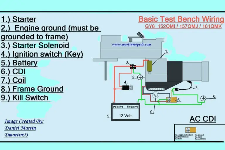
5 Pin CDI Wiring Diagrams
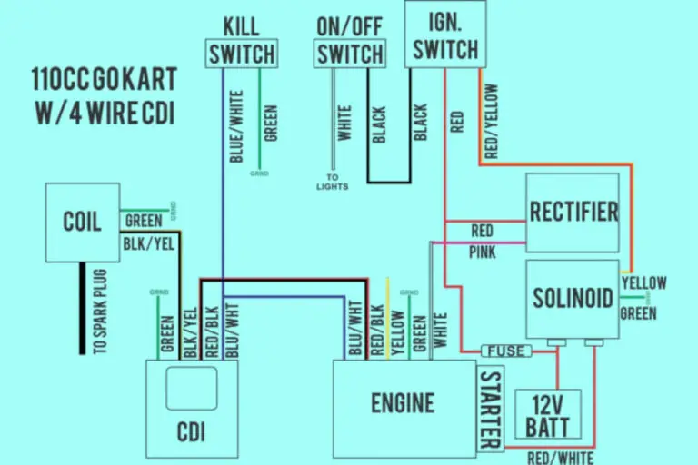
Diagram 1:

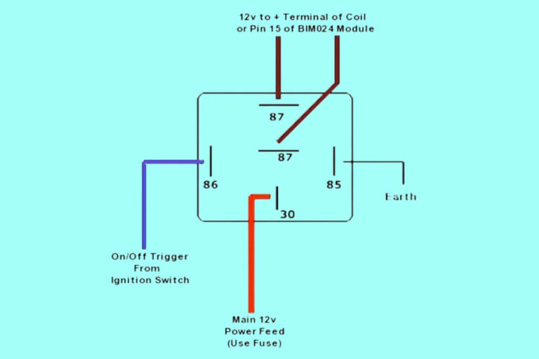
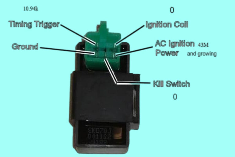
Diagram 2:

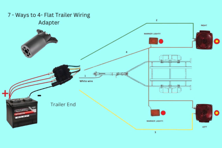
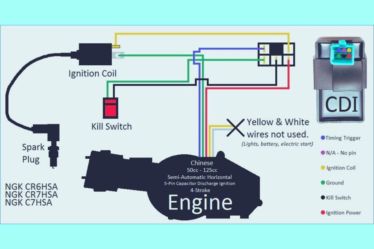
Diagram 3:

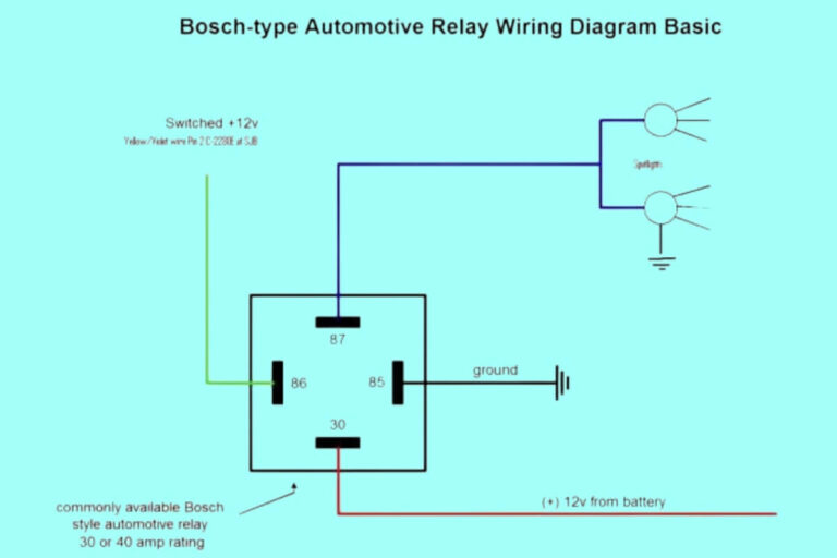
Diagram 4:
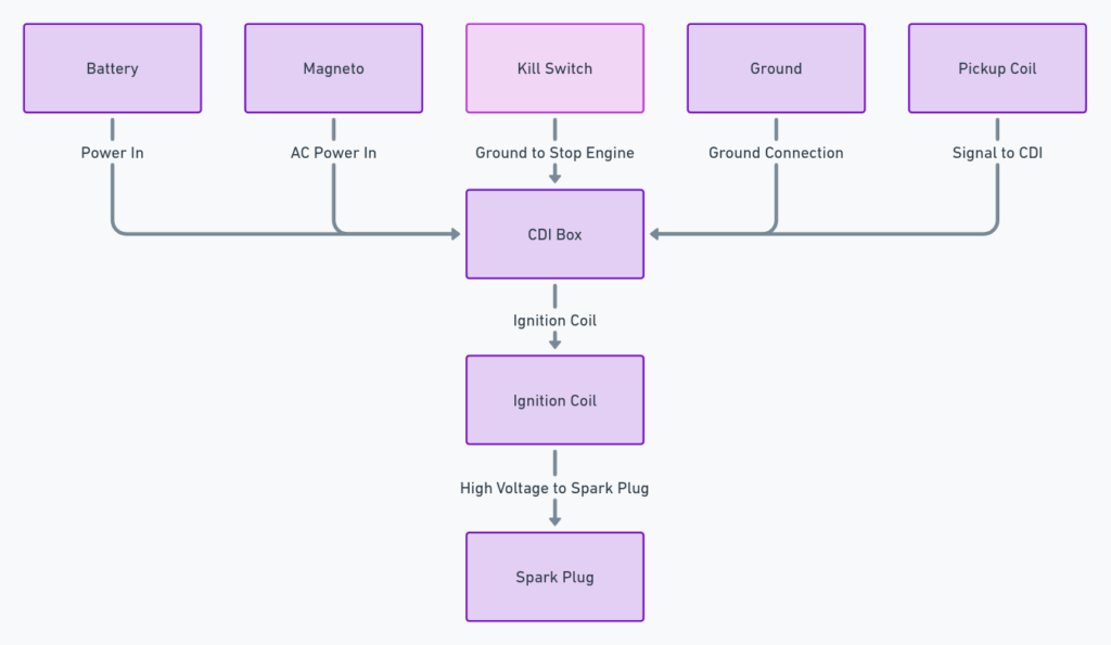
Diagram 5:

A 101 Background on Motorcycle CDI Ignition Systems
Before jumping straight to CDI pin diagrams, first we need to cover some ignition system basics in plain language.
CDI stands for “capacitive discharge ignition.” The CDI system improved upon the old inductive ignition points-and-contacts systems used in earlier motorcycles.
Instead of using breaker points that wore out quickly, CDI systems use rugged electronic components to control ignition spark timing and intensity. This translates into more reliable performance.
Here’s a simplified overview of how a basic CDI system works when cranking the engine:
- A capacitive circuit inside the CDI box stores hundreds of volts of potential charge.
- When triggered by a signal from the ignition pickup, an SCR switch flips closed.
- The CDI capacitor bank instantly discharges all its stored voltage straight to the ignition coil primary windings.
- This powerful pulse induces a super high volt spike on the ignition coil secondary windings that gets sent to the spark plug.
- The result is a nice fat spark inside the cylinder – ignition achieved!
Now let’s examine the wiring that ties all those CDI electronic components together…
Demystifying 5 Wire CDI Harnesses
CDI boxes always connect to two main types of motorcycle electrical circuits:
Power input – Provides juice to run the CDI box electronics Control wiring – Carries signals to and from engine sensors
On many bikes, power flows in from the battery on one big red lead, while four smaller gauge control wires handle ignition control signals.
This standard setup follows the classic “5 wire CDI” pinout pattern shown in wiring diagrams across manufacturers.
Now let’s walk through the function of each wire in detail.
CDI Power Wire (Typically Red)
This primary wire links the CDI unit’s battery input to a power source, either directly from the battery or via a kickstand safety switch.
CEetek and other manufacturers may use 14 or 16 AWG gauge red wire to handle the ~13-15 amp load. Proper power wiring is critical to avoid voltage drops that could cause intermittent CDI problems.
On bikes with electric start, this wire also activates the starter relay to crank the engine when you press the start button.
Note that some bikes split the power feed into multiple wires – like using one red wire for battery up, and a second orange wire for starter activation.
CDI Kill Switch Wire (Often Green or Blue)
This wire connects the CDI cut-off input to ground when you toggle the engine kill switch off. This cuts spark and stalls the motor.
When you turn the switch to “Run”, it releases the ground connection and allows the CDI box to fire normally.
CDI Ground Wire (Typically Black)
Every CDI system also needs a solid chassis ground backstop to complete the electrical loops through various ignition components.
The CDI box ground wire should connect directly back to the motorcycle battery’s negative (-) terminal. This gives a direct path to “dump” current from charged coils after each spark event.
If this ground circuit corrodes or gets disconnected, you may end up with problems like no spark at the plug cap.
CDI Signal Wire From Ignition Pickup (Usually Yellow)
This is where the magic happens! The thin yellow wire carries PWM (pulse width modulation) signals from your bike’s ignition pickup to tell the CDI box exactly when to trigger a spark event.
Pickups are basically sensing coils mounted beside a spinning rotor. Together they form a type of magnetic trigger that reads when metal lobes pass by the pickup coil’s tip.
The pickup translates timing imprints on the rotor into timed voltage spikes – essentially Morse code for when to pulse ignition coils! This timing data gets sent to the CDI circuitry to coordinate spark.
For instance on a 4 stroke motor, the pickup may generate four pulse signals per crank revolution so the CDI fires the plugs once every 360 degree cycle.
CDI Output Wire to the Ignition Coil (Often White)
Finally, the white CDI output wire carries that magical capacitor discharge current to the ignition coil’s primary windings each firing cycle.
This is the signal that ultimately transforms Battery/CDI voltage into gut-punching 100+ volt spikes needed to bridge the plug gap and ignite fuel vapor.
Pinout Wiring Diagrams by Motorcycle Brand
Now that you know basic CDI wire functions, next let’s explore connector pinout arrangements across major manufacturers.
Below are wiring diagrams showing CDI layouts across various makes according to wire color and pin position.
Honda 5 Pin CDI Wiring Diagram
On many Hondas, the CDI harness plugs straight into a rectangular connector on the CDI box. Typical wire layout:
- Pin 1 – Red – Switched power
- Pin 2 – Green – Kill switch input
- Pin 3 – Black – Ground
- Pin 4 – White – Coil signal output
- Pin 5 Yellow – Signal input
Yamaha CDI Wiring Connectors
Instead of a single plug, Yamaha motorcycles often use two separate connectors – smaller one for signals, larger for CDI power.
Yamaha signal connector:
- Pin A – Yellow – RPM sensor signal input
- Pin B – Green – Kill switch input
- Pin C – White – Ignition coil output
Yamaha power connector:
- Pin A – Red – Battery Source (switches to starter motor when activating electric start)
- Pin B – Black – Ground
Suzuki ATV CDI Wiring
Suzuki all-terrain-vehicles (ATVs) follow a similar convention of splitting the CDI harness into detachable signal and power plugs.
On the Suzuki signal connector:
- White/Yellow – Tach signal output
- White/Blue – RPM sensor signal input
- Green/White – Kill switch input
- White/Red – Coil output
The corresponding Suzuki CDI power plug pinout has:
- Red – Battery source
- Black – Ground
Note the consistent use of white background wires with various tracer colors for control functions.
As you can see, while wire colors may vary slightly between manufacturers or models, all 5 pin CDI boxes follow the same logical power, ground, activation, and signal wiring framework.
Now let’s shift gears and cover some key installation and troubleshooting topics.
CDI Wiring Dos and Don’ts
When dealing with CDI systems, here are some wiring best practices to avoid frustrations:
DO:
- Use exact wire gauge and insulation ratings recommended by the manufacturer
- crimp or solder + heat shrink all wire splices to ensure reliable conductivity
- Use protective wiring conduit around exposed sections prone to vibration or abrasion
- Seal CDI boxes thoroughly from dust, oil, and water intrusion
- Confirm bolt hole threading when swapping CDI mounting positions
- Verify all harness plugs seat fully before applying power
DON’T:
- Leave loose pin connectors unattended during installs
- Allow excess wires to flop loosely causing shorts
- Mix up Kill switch vs switched 12V+ wires! Double check functions.
- Forget to use spark tester tools like in-line indicators to validate coil firing
Diagnosing Faults from CDI Wiring Symptoms
Intermittent glitches in CDI wiring can cause all sorts of difficult-to-diagnose drive ability bugs or hard starting issues.
Here are clues to common CDI problems based on wiring symptoms:
No spark at plug:
- Loose or unplugged coil output wire
- Low/dead battery not supplying sufficient switched 12V+
- Damaged pickup not sending signal to CDI box
- Excess resistance in trigger wire causing weak signal
- Bad CDI ground connection
Spark but bike/quad won’t turn over:
- Check for improperly wired or damaged starter button
- Severe voltage drop on input power feed to starter motor solenoid
Cuts out or misses at high RPM:
- Worn ignition pickup winding allowing timing scatter
- Intermittent power drop to CDI unit
- Bad crimps/connections on sensor leads
Periodic misfire or backfire:
- CDI input wire picking up interference
- Arcing from loose high-tension coil lead
Use these symptoms together with five pin CDI wiring diagrams to zero in on issues through systematic wire inspection and testing.
Frequently Asked CDI Wiring Questions
Hopefully by now you’re much more confident reading wiring schematics for CDI ignition systems. To wrap up, here are answers to some commonly asked questions from motorcycle enthusiasts installing or debugging their CDI boxes.
How do I verify CDI spark strength?
The best way is using tools like an LED spark tester. This gives a real time visual verify that your coil is emitting a crisp, strong spark.
Compare readings among good cylinders vs problematic jugs to pinpoint wiring faults affecting spark intensity.
Why does my engine cut out when hot?
Overheating CDI boxes often suffer intermittent signal or output failures. Check for blocked cooling vents, damaged temperature sensors, or inadequate thermal protection on replacement CDI units.
What tools can test CDI wires?
Some experts recommend simple 12v circuit testers for checking basic power and continuity. For advanced signal analysis, digital storage oscilloscopes let you visualize and decode CDI waveforms.
How do I find CDI pinout diagrams for my specific MX bike model?
Check online OEM parts catalogs from the manufacturer, or forums dedicated your particular motorcycle brand and model. For instance, this site shares CDI pinouts for the ’88 Yamaha FZR600.
Why does my bike sometimes lose spark at the worst moments?
Flaky connections anywhere in the CDI input or high current output pathways can manifest as intermittent spark failures under vibration. Recheck all wiring joints and splices.
We hope these 101 pointers help add CDI systems to your troubleshooting toolkit and inspire diagnosing wiring issues more confidently after glancing at those cryptic wiring diagrams!
Our top tip? Start by confirming battery supply voltage entering the CDI, then methodically work forward verifying clean signals and connectivity.
What other motorcycle ignition wiring questions should we add to this guide? Comment below!

