Decoding 5 Pin Relay Wiring Diagrams in Vehicles
Relays are common components in any vehicle’s electrical system. By using a low electric current to control a higher electric current, relays allow components like headlights, fuel pumps, and car stereos to turn on and off without running high amp loads through the main switch or computer.
But how exactly does a 5 pin relay work, and how do you properly wire it?
A 5 pin relay uses an electromagnet to open or close a switch, allowing a low current circuit to control a higher current circuit. By properly connecting wires to the coil, input, output, and ground terminals, you can install a 5 pin relay for various automotive applications.
This guide will cover everything you need to understand 5 pin relay wiring diagrams, including:
- Essential parts and operation of a 5 pin relay
- Relay testing procedures using a multimeter
- Step-by-step installation and wiring instructions
- 5 pin relay diagrams for sample automotive applications
- Comparison to other 4 pin and 8 pin relay types
- Important terminology for understanding diagrams
- Troubleshooting common issues with wiring
So whether you need to install a new relay or decipher a confusing wiring diagram, use this resource to master 5 pin relays!
What is a 5 Pin Relay and Where is it Used?
A relay is an electrical component that uses a magnetic field to close or open a switch in one circuit based on conditions in another circuit. Relays consist of a coil, movable iron core, and switch contacts.
When power is applied to the coil, it generates a magnetic force that pulls the contacts closed, allowing full current to flow from input to output. 5 pin relays are a type of Single Pole, Double Throw (SPDT) relay that contain 5 terminals to connect various wires.
5 pin relays are commonly used in automotive charging systems, to control motors, solenoids, or other high current accessories:
- Headlight Relays
- Radiator Fan Relays
- Fuel Pump Relays
- Accessory Power Relays
Compared to more basic 4 pin relays, 5 pin relays offer greater flexibility for advanced automotive circuits by providing an extra terminal.
5 Pin Relay Wiring Diagrams
Diagram 1:

Diagram 2:
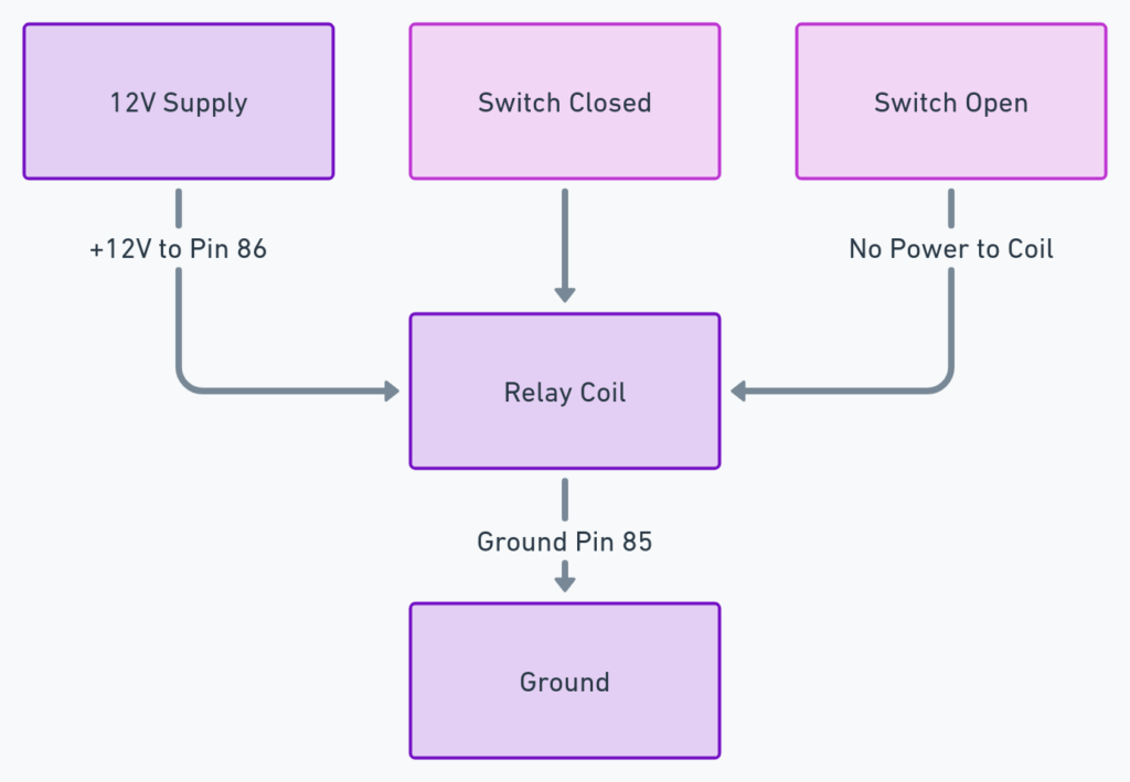
Diagram 3:

Diagram 4:

Diagram 5:

Essential Parts of a 5 Pin Relay
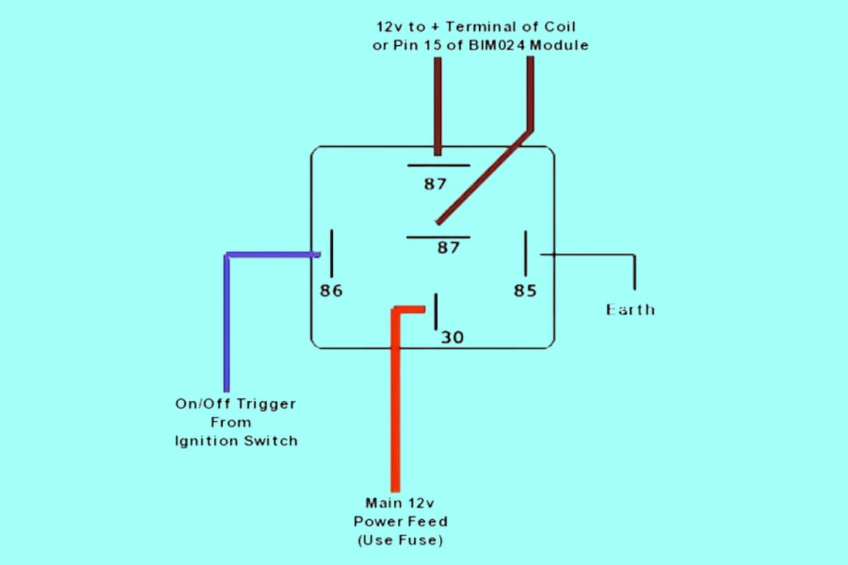
To interpret 5 pin relay wiring diagrams, you need to become familiar with the purpose of each terminal:
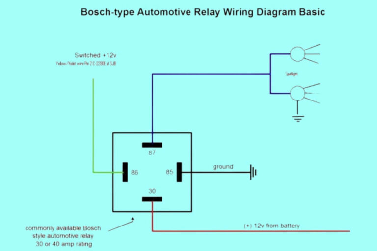
- Pin 85 / 86 – Coil Terminals: Applying 12+ volts to these pins forms a magnetic field that closes the switch. Typically powered from a separate control circuit.
- Pin 87a: Normally Open Contact – Connected to Pin 30 when the coil is powered.
- Pin 87: Common Switch Terminal – Can connect to 87a or Pin 87b depending on relay state
- Pin 30: Input from Power Source – Feed to component being controlled when relay activated
- Pin 87b: Normally Closed Contact – Connected to pin 87 when relay coil is off
So in summary, a 5 pin relay uses a magnetic coil to open and close contacts, allowing the low current control wires at 85 and 86 to switch power on pin 30. This SPDT relay gives flexibility to integrate normally open or closed contacts into our circuit design.
Next, we’ll cover how to functionally test a relay before wiring it into a car.
How to Test and Confirm Proper Function
Before installing your new 5 pin relay, it’s wise to test operation off the vehicle using a multimeter and power source. We can measure continuity across different pins to simulate coil activation.
You’ll need:
- 5 pin relay
- Multimeter
- Jumper wires
- 12V source (battery, power supply, etc)
Steps to Test 5 Pin Relay:
- Set multimeter to Continuity Test mode. This checks if electricity can flow across two points.
- With the coil NOT powered, check between pins 87 and 30. You should measure continuity.
- Check between pins 87 and 87b. Continuity should also exist here.
- Connect 12V+ from a power source or battery to pin 85, and ground to 86. This energizes the coil.
- Check continuity between pins 87 and 87a. The contacts have now switched closed.
- Remove 12V supply to deactivate coil. Continuity returns between 87 and 87b.
If your relay operates as described, you have confirmed the coil, switch contacts, and terminals function properly!
Next we’ll apply this understanding of a working 5 pin relay by installing and wiring it into a sample automotive circuit.
Wiring a 5 Pin Relay from Start to Finish
When wiring a 5 pin relay into your car, follow this general procedure:
- Determine relay location – find a suitable spot to mount it safely away from moisture or moving parts
- Connect Ground Black wire to chassis ground point
- Connect Control Trigger Wire from controller to Pin 85
- Connect Ground Wire from controller ground to Pin 86
- Connect Input Power Wire to terminal 30
- Connect Output Device Wire to terminal 87
This sequence first grounds the relay, then sends an activation signal from the controller to turn on the electromagnet coil. Power from the source is now switched by the relay to operate the output component.
Some examples:
- Turn on Headlights by having ignition circuit trigger relay, battery powering lights through output pin.
- Operate Electric Fan based on input signal from Engine Computer, temperature switch, or manually switched power.
Use the diagrams below as a guide for two common 5 pin relay wiring applications:
Headlight Relay Wiring Diagram
This diagram shows a SPDT relay wiring setup to amplify the headlight switch signal using full battery current. This prevents overheating damage to the switch from high beams.
Electric Fan Relay Wiring Diagram
Similar to headlights, an electric cooling fan places heavy amp load on switch circuits. By using an ECU Signal or Thermoswitch to trigger the electromagnet coil, a low current circuit controls battery power to the fan motor or element.
While these two examples utilized different activation methods, both used a 5 pin relay to control high current output devices. The relay serves as an amplifier of sorts – taking a small control signal to switch substantial loads.
Comparison to Other Relay Types
Besides the common 5 pin SPDT configuration, you may encounter other relays when working on your car. Comparison between popular options:
4 Pin Relays
- Very common general purpose automotive relay
- Less flexible with only 8 terminals
- No normally closed contact
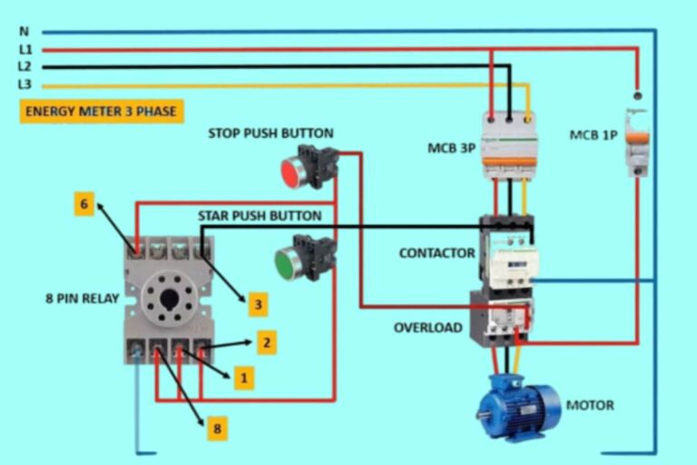
8 Pin Relays
- Allow independent control of two separate SPDT contact pairs
- Used for more advanced switching logic
- More expensive and complex to wire
For most applications, upgraded wiring kits include 5 pin relays to offer normally open AND closed switch contacts if desired. This gives the most flexibility for integrating into existing car circuits.
Important 5 Pin Relay Terminology
Reviewing the description of components so far, here are some key terms to help decipher relay wiring diagrams:
- Coil: Electromagnet windings that close switch when powered
- Normally Open – Default disconnected path when coil is off
- Normally Closed – Default connected path with relay deactivated
- SPDT: Single-Pole, Double-Throw – The two switch positions available
- Relay Socket: Mounting base relay inserts into
- Control Trigger: Signal to activate electromagnet coil
Learn these basic definitions when dealing with any relay circuit!
Troubleshooting Common 5 Pin Relay Issues
While relay problems can derive from wiring faults or bad connections, the relay itself can also cause issues. Here are some troubleshooting tips for 5 pin relay operation:
- No Activation: Check control/trigger voltage at Pin 85 while attempting to turn on circuit. If 12+V present, relay may be damaged.
- Constant On/Off: Indicates contacts shorted closed or open. Replace relay.
- Overheating – Contacts partially stuck closed causing resistance. Swap relay.
- Corrosion – For vital functions like fuel pump, install sealed relay if corrosion likely from water exposure.
Catching problems early prevents damage elsewhere in the wiring harness. Most relays prove reliable once properly installed, but mechanical wear or moisture ingress can shorten lifespan.
Best Practices for Automotive 5 Pin Relay Installation
Follow these guidelines when wiring 5 pin relays for optimal performance and longevity:
DO:
- Mount relay with ventilation for cooling if possible
- Use crimped, soldered, or properly twisted connections
- Confirm relay socket/base matches relay tabs
- Review wiring diagram to understand operation
- Connect “Trigger Wire” to proper signal source
DON’T:
- Force relay into mismatched socket
- Leave loose strand wires untwisted after crimping
- Mix up activation, ground, input or output wires
- Exceed recommended Coil Voltage
These simple wiring practices prevent self-inflicted headaches! Building clean relay circuits makes automotive electrical systems and wiring upgrades much more straight forward.
Conclusion – How to Read 5 Pin Relay Diagrams
Whether you’re installing fancy new off-road lights or repairing a fuel pump circuit, chances are you’ll encounter a 5 pin relay along the way. These handy components allow low current control circuits to switch heavy car loads by closing magnetic contacts, amplifying the control signal in a sense.
While appearing complex at first, interpreting 5 pin relay wiring diagrams simply requires understanding the function of the individual terminals. Using the guides above will have you navigating relay diagrams and troubleshooting circuits in no time! Finally, following good installation practices ensures reliability so you can keep the tunes pumping in your custom vehicle.

