Demystifying 6 Pin DC CDI Box Wiring Diagrams
Have you ever opened up your motorcycle’s side panel to check the ignite system and felt bewildered by the chaos of wires and connectors? And when you locate the CDI box, you find a bewildering array of different colors and gauge wires seemingly woven together at random.
You don’t just want to start randomly unplugging things, as improper connections can damage expensive electronic components. But without making sense of that rat’s nest, how can you even diagnose or fix any ignition problems your beloved bike might be having?
What exactly do all those CDI wires and connectors actually do? And more importantly, how can you use 6 pin DC CDI wiring diagrams to make sense of them?
The key is learning how to read and interpret motorcycle CDI wiring diagrams. These schematics serve as a roadmap to visually trace the wire harness paths and understand the purpose and logic of each connection from component to component.
In this post, we’ll guide you through decoding these potentially mystifying documents step-by-step. With the ability to accurately reference 6 pin cdi wiring diagrams, you’ll gain confidence in troubleshooting ignition issues and maintaining peak engine performance on any 150cc, 200cc, or 250cc motorcycle.
Specifically, we’ll review:
- CDI box basics – what they do and why they matter
- 6 pin CDI wiring diagram layouts and conventions
- Connecting power, ground, and signal wires properly
- Using diagrams from service manuals for your specific motorcycle
- Leveraging wiring schematics to diagnose ignition problems
- Safety tips for working with motorcycle wiring harnesses
So let’s get started demystifying those complex boxes of wires!
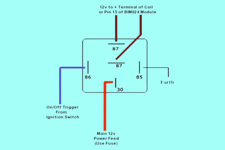
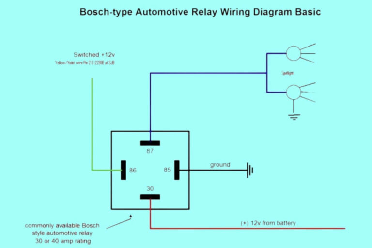
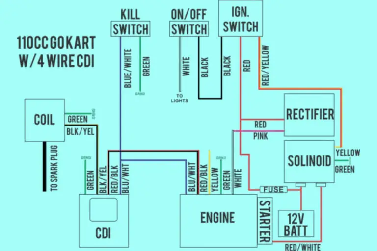
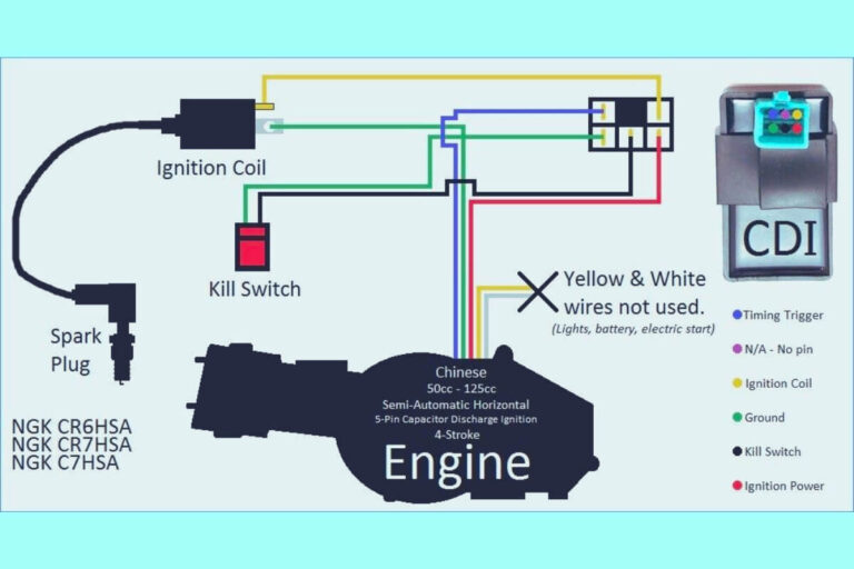
6 Pin DC CDI Box Wiring Diagrams
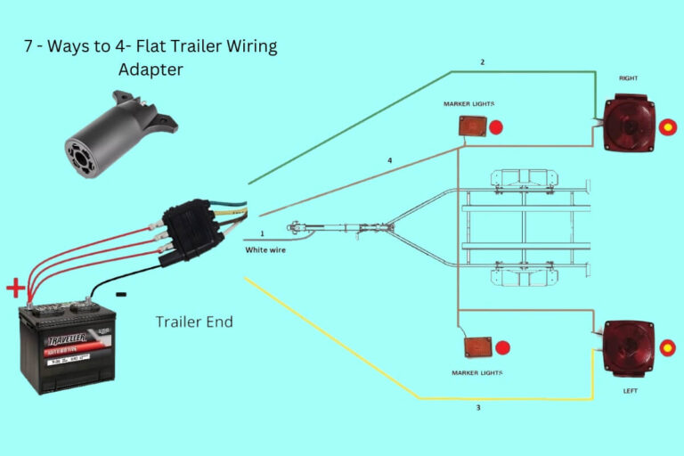
Diagram 1:

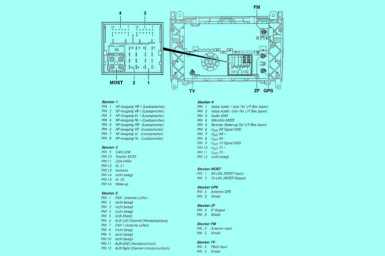
Diagram 2:
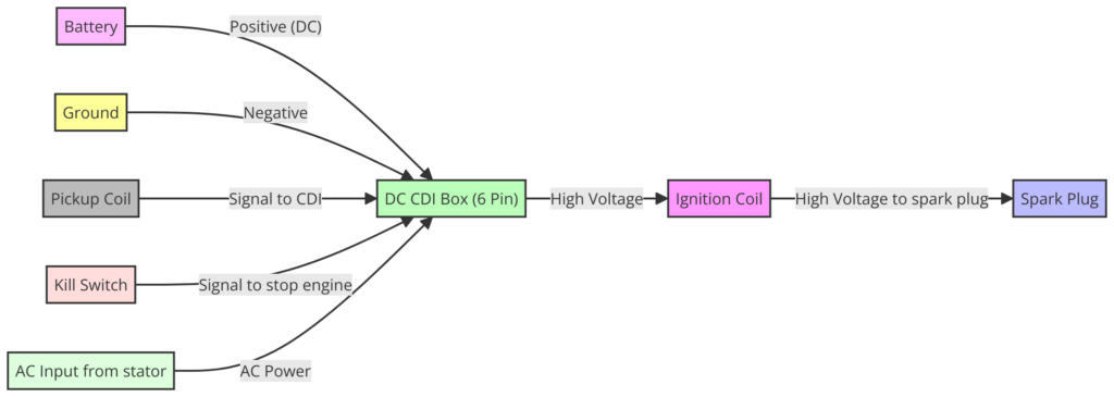
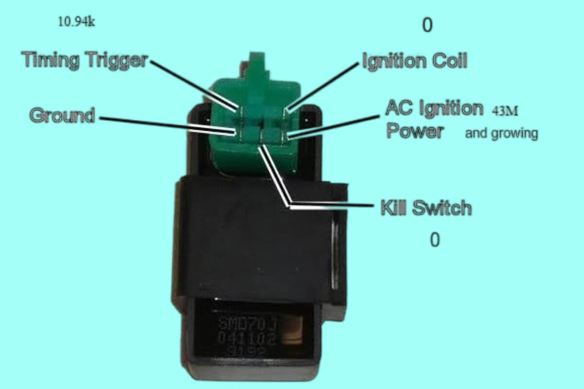
Diagram 3:

Diagram 4:

CDI Box Basics – The Brains of Your Motorcycle’s Ignition System
The CDI box or “Capacitor Discharge Ignition” unit is essentially the brains responsible for controlled timing of the high-voltage charges sent to your motorcycle’s ignition coils.
Without the CDI properly activating the ignition coil at just the right millisecond, the engine will fail to fire at all or will run very poorly. CDI issues can cause anything from a slight performance decline to a non-starting bike.
There are two main types of CDI boxes:
- AC CDI boxes – Typically used on older or smaller displacements bikes. Rely on alternating current from charging coils or magnetos to generate their internal voltage signals.
- DC CDI boxes – Found on more modern and larger motors. They have an internal voltage regulator to convert input power to consistent DC current signals.
Within DC CDIs, the most common variety for Chinese-made 150cc-250cc motorcycles is the 6 pin DC CDI box. These have specific connectors and wiring to handle multiple control channels, powered sensors, and DC voltage regulation.
Because of their complexity compared to basic AC CDI boxes, interpreting 6 pin dc cdi wiring diagrams is critical for diagnosing and fixing issues with the ignition system. The wiring connects all of the related components, and problems can occur anywhere in that system – the CDI box itself, the signal sensors, ignition coils, or the wiring harness.
Let’s examine how professionals visually map all those connections using wiring diagram schematics.
Orienting Yourself to the Wiring Diagram Landscape
At first glance, a wiring schematic like that above can look like a big jumble of wires and components. But like reading any map, you need to get oriented to the major landmarks and understand the basic visual language.
The major components in a 6 pin DC CDI wiring system are:
- CDI Box – The black box at the center handling ignition timing
- Battery – Provides incoming power to the CDI electronics
- Ignition Coils – Generate high voltage spark for each cylinder from CDI timing signals
- Signal Pickups – Sense engine position/RPM and feed to CDI for timing
- Spark Plugs – Receive timed high voltage pulses from ignition coils to ignite fuel
Fortunately, CDI wiring diagrams use standard visual conventions across all manufacturers and models:
- Power and ground connections are shown in red and black wires respectively
- Green wires indicate electronic signal pathways
- Connector pinouts are drawn with their real shapes and pin counts
- Components and connectors have text labels identifying them
Additionally, dotted lines show hidden wire paths, while solid lines indicate visible cable runs – like you’d see under the side fairing.
Having a wiring key like this diagram makes the various connections much less abstract. Just remember: red = power, green = signals, black = ground.
Connecting the Wires Correctly
Let’s walk through the purpose of each connector systemically:
The main CDI connector links all the control electronics to the engine components they actuate:
- Pins 1 & 2 – Ground wires back to the negative battery terminal
- Pins 3 & 4 – Input signals from engine position sensors for timing
- Pins 5 & 6 – Outputs to ignition coils commanding them to fire spark plugs
Note the two separate grounds – this gives redundant paths back to power source if one connector shorts out or fails for some reason.
The CDI requires confirmation from both sets of sensors before activating the coils, ensuring very precise spark timing. Without properly shielded and connected control wires, erratic CDI behavior occurs.
Next is the AC Generator connector:
- Yellow wires – Carry lower voltage AC power generated from engine rotation for battery charging
Then the Ignition Coil connectors have:
- Thick red wires – Main +12V DC power supply – sometimes connected via a separate fuse
- Green wires – The critical signals from CDI box determining ignition timing
- Black grounds – Complete the power circuit back to the battery
Getting clean power and solid grounds through quality wiring is vital for the CDI system. So that covers the basics of identifying connectors by color and purpose on the wiring diagram.
Finding the Correct Diagram for Your Motorcycle
Now that you understand the components and connector types, we need to locate the right schematic for your bike.
There are three main options:
- Motorcycle service manual – Printed manuals from the OEM will contain detailed wiring diagrams covering CDI connections and all other electrical systems. This should be your primary go-to resource.
- Online parts fiche – Most manufacturers now have online parts lookup tools showing some degree of wiring details. Quality varies widely so printed manuals still reign supreme.
- Aftermarket diagrams – If options 1 and 2 fail, lots of universal 6 pin CDI wiring diagrams for Chinese engines are available online. But making any required adaptations is on you!
Within these resources, you need to identify diagrams specifically showing the 6 pin DC CDI box. Some other diagrams cover simplified AC CDI wiring only or other systems like lighting.
Let’s look at some real-world examples across different bikes:
Lifan 200cc Engine
This shows a universal DC CDI diagram from a Lifan 200cc motor found on many knock-off pit bikes. Note 6 pin connector at center and follow green signal wires from sensors through to twin ignition coils.
Honda CBR250
This excerpt from a Honda CBR250 manual has similar circuit logic but uses a variant CDI connector specific to this model. Wiring colors also differ from the generic Lifan diagram above.
Yamaha Raptor ATV
As an ATV-specific example, this Yamaha Raptor schematic shows both CDI and AC generator functions combined into one box. But at the pinout level, similar ground, power, and signal wires connect through to the ignition coils.
The key across all OEM diagrams is identifying wire colors and counting connector pins rather than assuming a generic layout. Components may be combined or connectors rearranged, but the electrical circuits perform the same underlying functions.
After some comparison review, you start to pick out common CDI wiring patterns. And as you become familiar with using service diagrams for your specific motorcycle or ATV, they transform from indecipherable spaghetti to a useful troubleshooting aid.
Leveraging Wiring Diagrams for Diagnosing CDI Problems
With a solid understanding how to read them, 6 pin dc cdi wiring diagrams provide a powerful diagnostic tool for all manner of ignition problems:
- No spark issues – Methodically check continuity through connectors and harness wires pin by pin to isolate faults. Assess ignition coil primary and secondary resistance.
- Intermittent issues – Wiggle wiring harnesses while running to check for shorts. Inspect connections for corrosion or damage.
- Weak sparks – Test stators, charge coils, regulators, and grounds for out-of-spec output due to worn windings or bad solder joints.
- Timing problems – Use wiring colors to carefully follow signal pathways back to sensor origins and check their air gap clearances.
- Aftermarket farkles & accessories – Trace intended wire modifications versus dangerous taps that may have damaged factory CDI wiring.
Many times, the original CDI box itself is fine, and problems arise elsewhere downstream. Wiring schematics combined with multimeter measurements help isolate whether issues stem from bad grounds, low power supply, sensor gaps being off, faulty solder joints, or plain old worn out wiring and connectors.
While some trial-and-error may still occur during diagnosis, that necessary reverse-engineering becomes much easier with the motorcycle maker’s wiring map at hand.
Safety Tips for Working on Motorcycle Wiring Harnesses
Before digging into troubleshooting your CDI system, a quick note on working safely with motorcycle wiring:
- Always disconnect the negative battery cable before disconnecting any components to avoid shorts
- Don’t just start cutting or splicing cables without checking a wiring diagram first
- Protect exposed wire ends and connectors from accidental touching
- Wrap or shield any inline splices you may need to prevent shorts
- Avoid tapping accessory power feeds from CDI system wires directly
- Confirm solid battery and grounds before powering up
Taking care handling motorcycle wiring can save you from hazardous shorts, damaged electronics, and frustrating rework down the line.
Decode Your CDI Wire Connections with DIY Confidence
In summary, while they may appear intimidating at first glance, 6 pin dc cdi box wiring diagrams provide a valuable roadmap for preventative maintenance and resolving ignition issues on your 150cc, 200cc, or 250cc motorcycle.
Learning to accurately trace and test those small colored wires from connector to connector unlocks DIY capabilities and can save you lots of headaches (not to mention dealership repair bills!).
We encourage you to seek out the appropriate OEM CDI wiring diagrams for your specific motorcycle or ATV make and model. Having that expert wire schematic along with the connector pinouts and wire color coding can make aftermarket troubleshooting much safer and easier.
So grab a multimeter and a service manual, and enjoy decoding that wiring puzzle! Let us know if you have any other questions – we hope you’ll find our wiring discussion here valuable in your repair and enhancement projects. Ride on!

