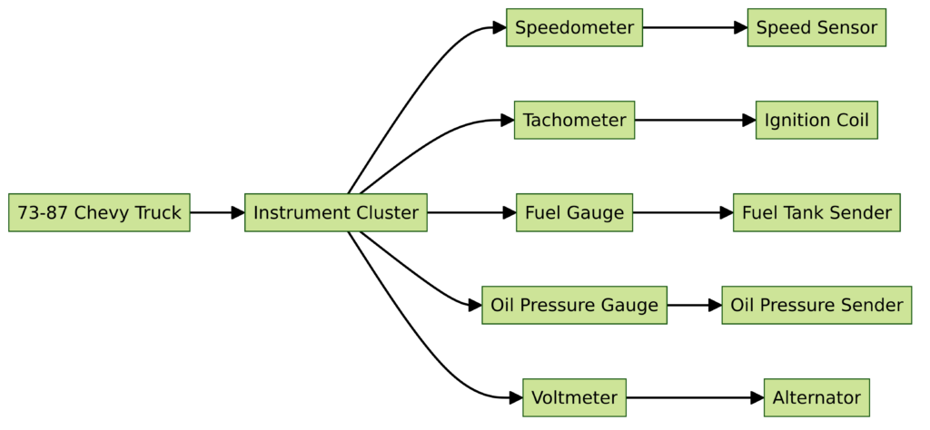
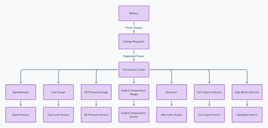
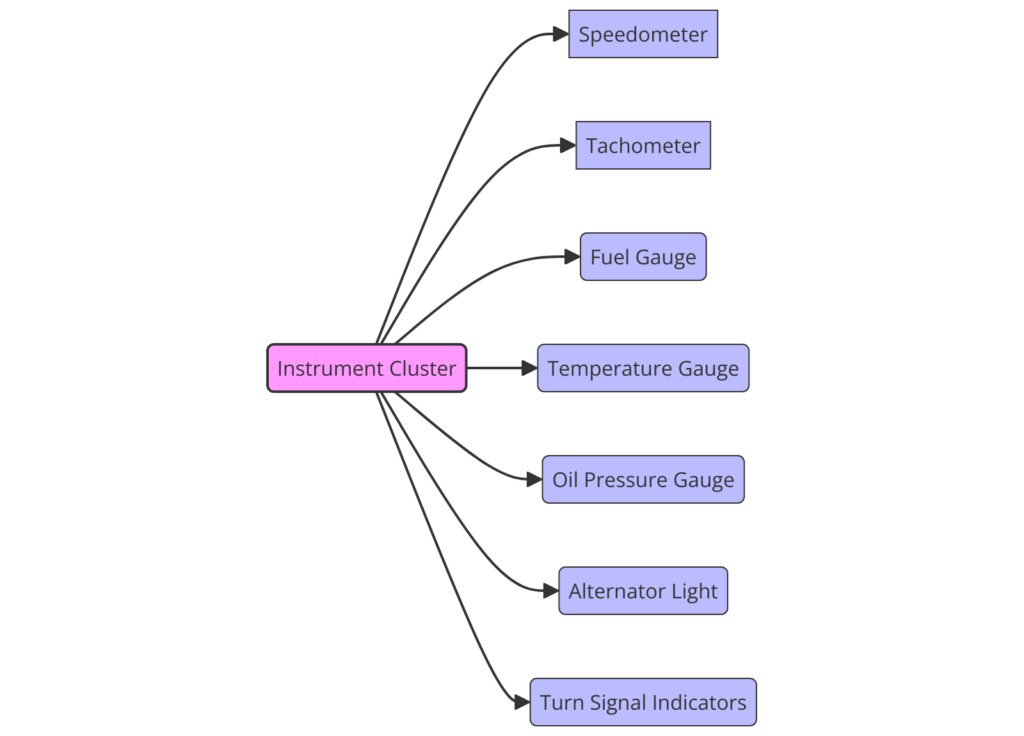
73-87 Chevy Truck Instrument Cluster Wiring Diagrams
The instrument cluster is the control center inside your truck, housing components like the speedometer, tachometer, and various indicator lights. Proper wiring is crucial for these gauges and lights to function accurately.
Wiring diagrams serve as “road maps” detailing the electrical connections between all devices in these clusters. While they may look complicated initially, breaking things down step-by-step removes the mystique around deciphering them.
Understanding these diagrams properly allows you to troubleshoot issues, ensure gauges work correctly after installing upgrades like tachometers, and know where wiring faults may exist if you need to repair damaged harness connectors down the road.
73-87 Chevy Truck Instrument Cluster Wiring Diagrams
Diagram 1:

Diagram 2:

Diagram 3:

Diagram 4:

Diagram 5:

Key Elements of 73-87 Chevy Truck Instrument Cluster Wiring Diagrams
Some standard elements are consistent across all 73-87 Chevy Truck wiring schematics related to instrument clusters. Being aware what these symbols and labels represent removes much complexity when first glancing at the diagrams:
- Wire Colors – Diagrams use standardized colors to represent each wire, like pink, yellow, black, and more. These colors tell you which wire bundle or harness a particular wire runs through.
- Connectors – Shows where wire harnesses plug into various instruments and fuse blocks. Identifying connectors helps locate where issues may exist.
- Splices – Indicates where wiring branches off to multiple devices. Useful for tracing specific wires back to origin points.
- Fuse Panel Sources – Denotes where power originates from for all key systems.
- Gauge/Light Labels – Identify all gauges, indicator lights, and switches for easier orientation around what wiring powers what device.
Once comfortable with diagram fundamentals, it becomes much simpler tracing where wires route, the components they connect, and where to start diagnosing problems.
Step-By-Step Walkthrough on Reading 73-87 Chevy Truck Wiring Diagrams
Rather than seeming like a jumble of wires and devices at first glance, treating diagrams as a logical series of connections makes diagnosing and working with instrument cluster wiring very straightforward. Here is one effective step-by-step approach:
- Identify the power source – The fuse panel is always the starting point from which current flows through to components. Note which fuse or relay provides power.
- Follow wire color paths – Use wire colors to follow the path from power sources to each device. Make mental notes on routes and connections.
- Note splice points – Pay attention to splice locations where wiring branches off to multiple endpoints. Tracing wires back to splices can help identify faults.
- Confirm endpoints – Verify where wire color routes terminate at devices like gauges or switch connectors through entire process.
- Relate to physical clusters – Finally, correlate the logical wiring you traced back to the actual components inside your instrument cluster for simplified troubleshooting.
With this reliable methodology, confusion disappears quickly even when interpreting complex diagrams showing dozens of wire routes!
Common Questions Around 73-87 Chevy Truck Instrument Cluster Wiring
Some typical questions owners have around decoding cluster wiring schematics include:
How to Tell What Gauge Each Wire is For?
Tracing wire color paths from devices to power sources reveals what each wire controls. Labels also clearly identify individual gauge functions.
What Do Connector Numbers Represent?
These indicate corresponding physical connections on wiring harnesses. So C101 would plug into a mating C101 connector elsewhere.
Where Do I Start Diagnostics for Gauge Issues?
Begin at power sources, then methodically follow wire routes to gauge endpoints while inspecting connections.
How to Confirm Diagram Matches My Exact Truck Configuration?
Carefully taking note of colors and harness connectors in your cluster allows directly matching real components to wiring diagrams.
With some familiarity around interpreting fundamentals, diagrams align logically with truck layouts.
Final Thoughts on Chevy Truck Instrument Cluster Diagrams
At first glance, the intricacy of circuit schematics showing complex instrument cluster wiring can certainly appear daunting. However, equipping yourself with knowledge around key diagram components removes nearly all difficulty in navigating these “road maps”.
Whether your goal is seamless troubleshooting, custom gauge upgrades, or repairing damaged harness connectors, we’ve untangled instrument cluster mysteries to prepare you for all wiring tasks on your 73-87 Chevy truck! Implementing a structured walkthrough when decoding diagrams also brings confidence.
Soon you’ll navigate intricate schematics effortlessly. And diagnosing or enhancing that aging cluster becomes much simpler when these blueprints to electrical systems no longer contain secrets waiting to be uncovered. Grasping the fundamentals transforms confusion into clarity.
