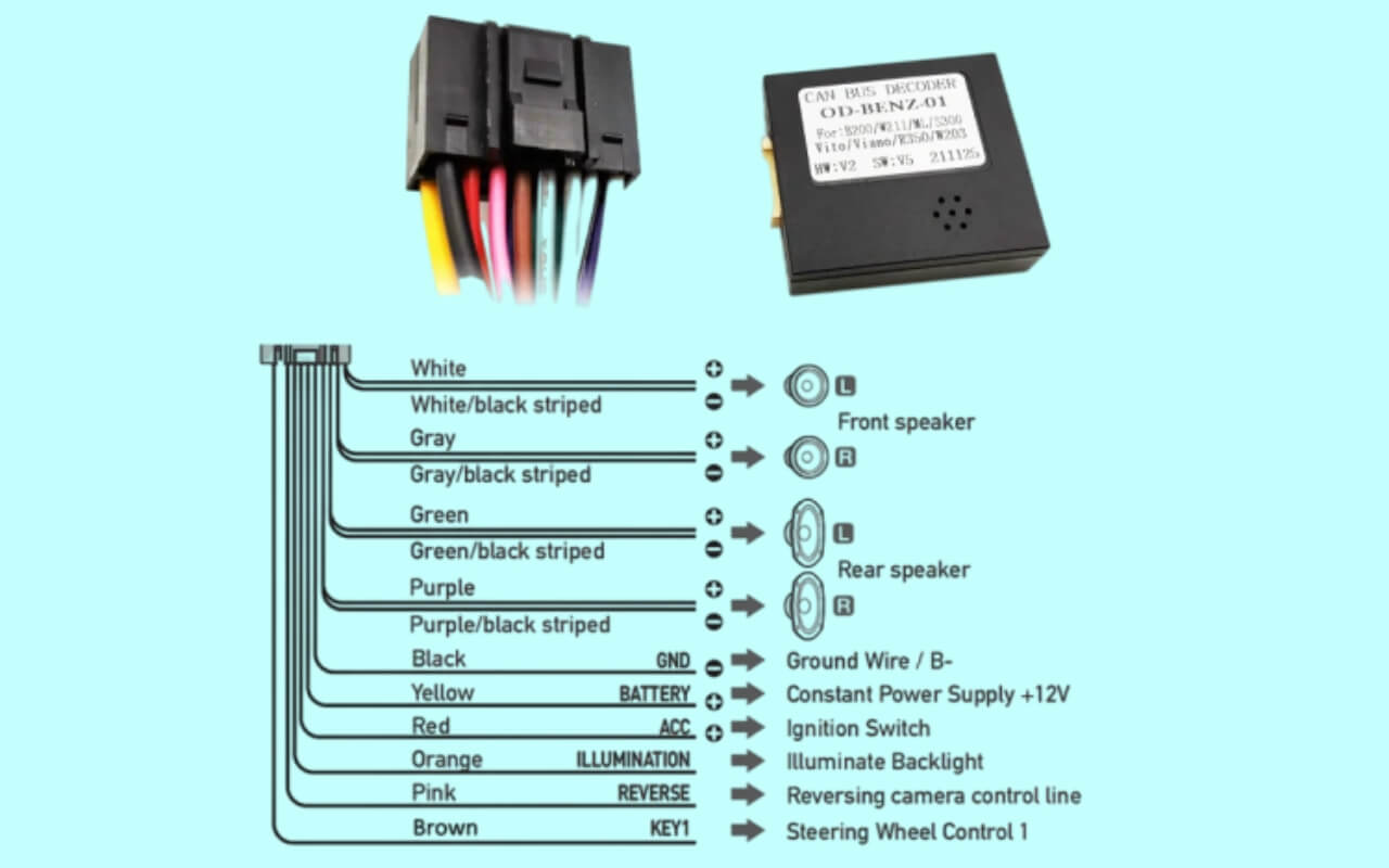
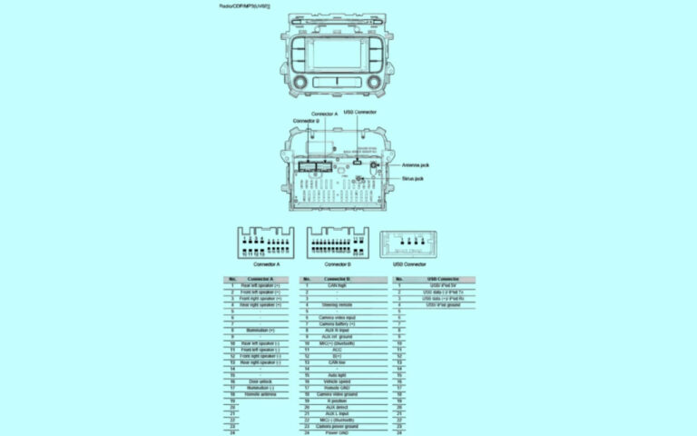
CAN Bus Decoder Wiring Diagram: A Beginner’s Guide

Have you ever wondered what that tangled mess of wires under your car’s dashboard does? What about that mysterious 16-pin port that mechanics plug tools into to access computerized data about your vehicle? Behind the scenes, your vehicle relies on an intricate communication network called the Controller Area Network or CAN bus to share information between components.
The CAN bus protocol manages data flow between the engine control unit, sensors, airbags, audio system, locks, and countless other systems over a simple two-wire interface. But while the CAN bus itself is straightforward from a wiring perspective, decoding and interpreting the data it carries requires some special tools.
So if you’ve ever wanted to tap into your ride’s nervous system to extract performance metrics, monitor sensors in real time, or integrate custom gadgets like smartphone apps, remote car starters, or backup cameras, this article will be your guide.
I’ll answer common questions about topics like:
- How CAN bus wiring works and what those wires actually do
- Essential hardware like OBD2 connectors, cables, and termination resistors
- What CAN bus packets and broadcasts actually contain
- How to decode CAN messages with various analyzer tools
- Steps for building your own CAN bus data logger device
And much more. Let’s dive in!
CAN Bus Basics: What is it and Why it Matters
The modern automobile relies on electronic control units (ECUs) to manage engine, transmission, safety, infotainment, climate control, security and countless other subsystems. The CAN bus acts as the car’s central nervous system, enabling all these components to communicate critical data by transmitting messages up to 64 bytes long via the twisted pair cable.
CAN stands for Controller Area Network, and the protocol was originally developed in the 1986s by Bosch for use in vehicles, although today we see it in maritime, aerospace, industrial, and even some home/office automation applications.
Some of the most common reasons to tap into your vehicle’s CAN bus wiring include:
- Diagnosing issues and accessing sensor measurements not exposed through OBD2
- Enhancing dashboards with additional gauges or performance displays
- Extracting data for racing applications like track telemetry
- Remote monitoring of a fleet vehicle’s status and location
- Adding aftermarket electronics like backup cameras and radar detectors
- Voice control or automation with digital assistants
Many modern vehicles have multiple CAN busses serving different subsystems, a primary high speed bus for critical operation and a separate single wire CAN bus for infotainment, climate controls, etc. The diagnostic port adheres to the OBD-II standard so work with any scanner tool.
Demystifying the CAN Bus Wiring Diagram
From an electrical perspective, the CAN bus topology uses just two wires for transmitting all data: CAN high and CAN low. The network relies on a differential balanced signal, not unlike RS-485. By sending CAN messages across a twisted pair cable, electromagnetic noise gets cancelled out at the receiving end.
The twisted pair wires connect to a standard 9-pin D-Sub connector, usually located below the dashboard, driver’s side. You’ll access this port when plugging in OBD2 scan tools and CAN bus data loggers. Most scan tools use pins 6 (CAN High) and 14 (CAN Low) but may also utilize the GND (pin 4) and 12V power (pin 16) lines.
The maximum recommended cable length for a CAN bus is 40 meters end-to-end, with lengths over 500 meters requiring a 120 ohm terminating resistor at each end. Always use high quality, shielded twisted pair such as Belden 3084A.
Importantly, CAN relies on a non-destructive arbitration system to avoid data collisions on the bus. If two ECUs transmit messages at once, every node will still receive the highest priority message in full. Lower priority incomplete messages get automatically retransmitted when the bus is free.
CAN Bus Data: Bits, Bytes and Baud Rates
A CAN network transmits data using a cleverly devised frame structure within a fixed 8 byte packet:
| Field | Length | Description |
|---|---|---|
| Start of frame | 1 bit | Denotes next bits are frame contents |
| Identifier | 11 or 29 bits | Priority and message type |
| Substitute Remote Transmit Request (RTR) | 1 bit | Reserved in CAN 2.0, used for remote transmission requests in CAN FD |
| Identifier Extension Bit | 1 bit | Switches between 11/29 bit ID |
| Reserved Bit | 1 bit | Unused but should be 0 |
| Data Length Code | 4 bits | Number of data bytes to follow (0-8 in standard CAN, up to 64 in CAN FD) |
| Data field | 0-64 bytes | Actual message content |
| CRC | 15 bits | Frame check value |
| ACK slot | 1 bit | Transmitter sends dominant, receivers send recessive to acknowledge |
| ACK delimiter | 1 bit | Must be recessive (1) |
| End of frame | 7 bits | Bus idle state |
This standardized frame results in very efficient and resilient communication even at blazingly fast speeds.
The maximum signaling rate depends on cable length due to propagation delays. Common CAN bus baud rates range between 33.3 kbps up to 1 Mbps. Newer vehicle models take advantage of a flexible data-rate (CAN FD) extension supporting up to 64 bytes of payload and bitrates as high as 10 Mbps.
Higher throughput equates to more sensor data flowing across the buses to feed advanced driver assistance systems, infotainment and an ever growing array of CAN bus enabled features.
Interfacing with the CAN Bus to Read and Decode Data
Now that we understand how CAN bus wiring and communication works at the physical layer, how do we actually read and decode all that data from our own projects? There are a few common approaches:
OBD-II Scanners
Many cheap OBD2 Bluetooth adapters and pro level scan tools like those from SnapOn can read diagnostic trouble codes and sensor measurements like RPM, vehicle speed, etc. This is certainly the simplest approach but lacks low level CAN bus access.
Development Boards
Hobbyists often leverage Arduino, Raspberry Pi, or similar microcontroller development boards with CAN bus controller shields for easy data logging and prototyping. The Seeeduino or SparkFun CAN bus shields make this plug-and-play.
You’ll still need software to actually parse and interpret the raw CAN frames. Boards with more horsepower like Pi’s can run advanced CAN tools natively whereas Arduino sketches would need to decode within tight program storage limits.
Dedicated Analyzers
Standalone CAN bus analyzers connect directly via DB9 or OBD port and ship with Windows/Mac software to interpret, graph, and export CAN data. These devices cost a few hundred dollars but combine wide compatibility with advanced capabilities for reverse engineering ECU behavior down to the signal level.
CAN to USB Interfaces
For pure data extraction, inexpensive CAN to USB interfaces float around eBay and AliExpress for ~$15. Mostly aimed at small embedded development, they convert CAN bus to serial or USB for piping into other software solutions. Lacking any intelligence, it’s up to your laptop or application for decoding the 0’s and 1’s.
DIY CAN Bus Sniffing and Decoding
Interfacing with the CAN bus gets more versatile when you assemble your own analyzer or data logger device. While ready-made adapters and OBD scanners work for basic diagnostics, a custom setup lets your board speak CAN fluently.
Here’s how to tap into a vehicle’s CAN bus wiring yourself:
Parts and Supplies
- Development board such as Arduino UNO, Pi Zero, or similar
- OBD2 Breakout Board such as Seeed Studio v2
- CAN Controller Board like Seeeduino or SparkFun CAN Bus Shield
- Twisted pair wire, resistor, solder, etc
CAN Bus Wiring Guide
- If using a breakout board, connect pins 6 and 14 to mate with CAN High and CAN Low
- Solder ~120 ohm resistors across CANH and CANL to VCC and GND
- Bridge CAN bus boards to development board via SPI or UART
- Load platform software like Raspbian OS, Arduino IDE
- Install SocketCAN, Python libraries, or IDE with CAN support
- Write software to parse CAN frames, output data to screen, file, cloud
For example code and selective decoding of CAN messages, check the links towards the end of this guide.
Advanced Concepts for CAN Bus Communications
While the basics of CAN bus wiring and data are covered above, we should briefly touch on terminology you may encounter with vehicle networks:
CAN FD and Flexible Data Rate – As mentioned earlier, CAN FD builds on the legacy CAN 2.0B bus specification by allowing larger data payloads and faster baud rates. This keeps CAN relevant for future vehicle complexity.
ISO 11898 – The ISO standards define CAN bus implementations for road vehicles, describing maximum lengths, logical requirements and conformance testing and more.
SAE J1939 – The SAE J1939 standards define how commercial vehicles like tractors and heavy trucks format CAN bus data traffic. Light vehicles adhere to the CAN standard ISO 15765.
CANopen – CANopen, like J1939, is an upper layer protocol that standardizes device and application profiles, configuration management, and how nodes interact. Widely used in automation equipment.
In Summary…Key Takeaways
The CAN bus serves as the vehicle’s communication backbone, carrying potentially thousands of signals to dozens of electronic control units. While CAN networks carry simple 1’s and 0’s, decoding and leveraging this data requires compatible hardware, the right software tools and an understanding of how the messages are structured.
We broke down the fundamentals around:
- CAN bus topology and typical OBD-II connector pinouts
- Decoding CAN frames containing sensor measurements and status
- Bit rates, baud rates, ideal cable lengths and termination resistors
- Interfacing options such as OBD-II adapters and CAN controller boards + dev kits
- Steps for wiring your own DIY CAN tap and things to watch out for
Hopefully by now you have a solid high level overview of how CAN bus wiring works and what’s involved in interfacing with those simple two wires. Automotive computing technology will only accelerate as more sensor data gets processed for self driving functionality. CAN bus analyzers help make sense of that data today but could be tomorrow’s black box flight recorder.
Either way, I’m excited to see what CAN-enabled projects this community dreams up next using the knowledge from this guide!


