How to Read Wiring Diagrams: A Step-by-Step Guide
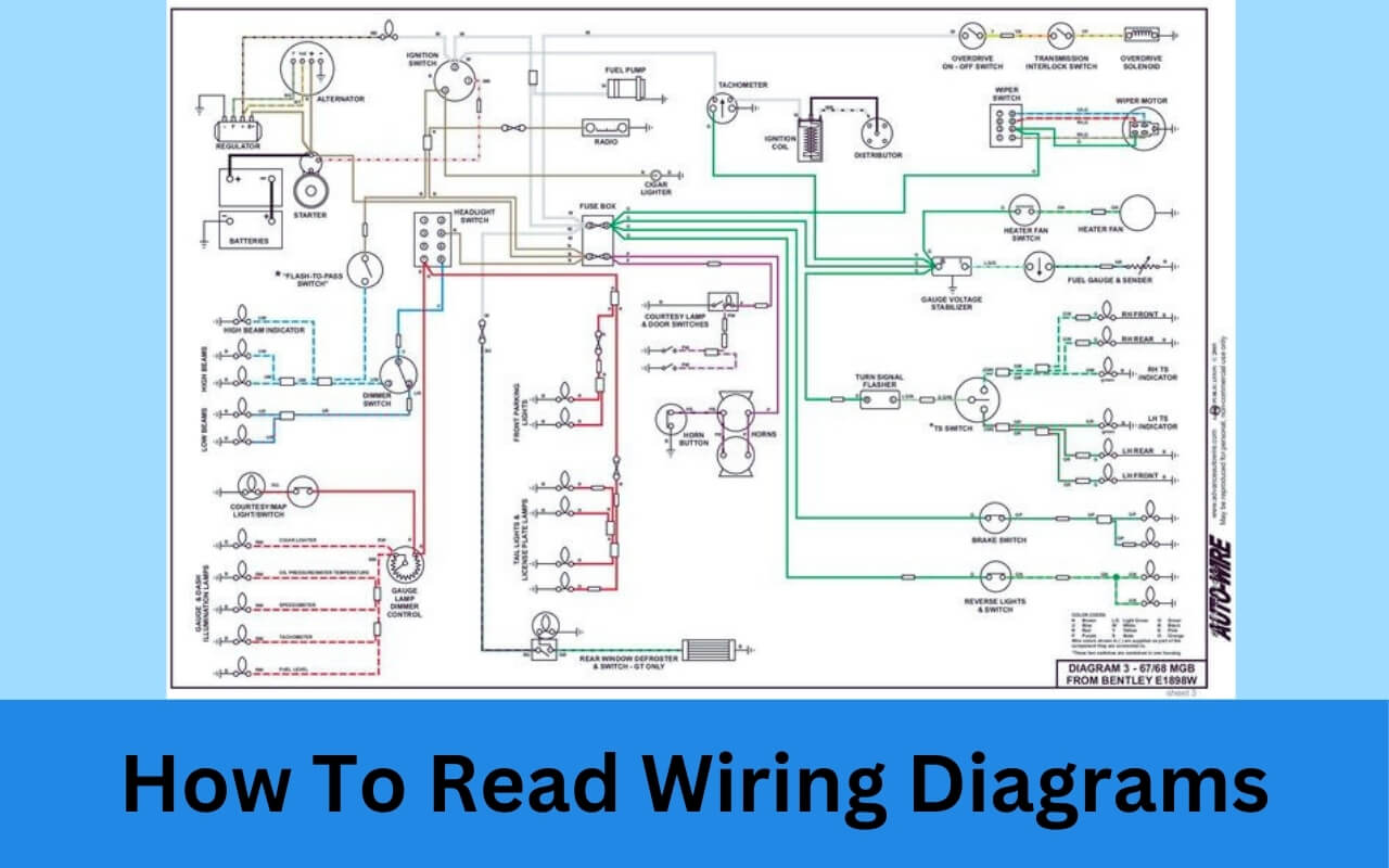
Have you ever opened up a wiring diagram and felt completely lost trying to make sense of the mess of lines, symbols, and abbreviations? As an electrician, technician, or do-it-yourselfer, having the ability to read wiring diagrams is an essential skill for working with electrical systems and equipment.
But where do you start when looking at a complicated circuit diagram? How do you know what all those symbols and connectors mean? Why should you even bother learning how to decipher complex schematics?
The ability to read and understand wiring diagrams is critical for properly installing, troubleshooting, and designing electrical circuits and systems. Failing to comprehend the intricacies of an electrical drawing can lead to incorrectly wired equipment, safety hazards, frustrating technical problems, and costly mistakes.
In this post, we will answer the question: How do you learn to read a wiring diagram? We’ll examine exactly what a wiring diagram is, why it’s important to know how to decipher them, identify common symbols you’ll encounter, and provide a step-by-step guide to reading any wiring diagram like a pro.
By the end, you’ll have the knowledge to confidently open up any electrical wiring diagram and understand exactly what is going on in the connections, components, and current flow. Let’s get started!
What Is a Wiring Diagram?
Before jumping into the specifics of reading a wiring diagram, let’s make sure we understand exactly what a wiring diagram is and how it’s different from other types of circuit drawings.
In simple terms, a wiring diagram is a visual representation showing how electrical components are interconnected. It uses standard symbols to represent the various components in a circuit and lines to demonstrate how they are connected together.
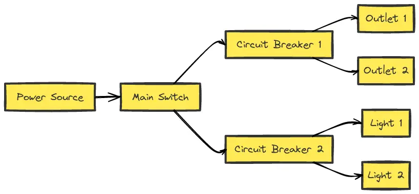
Wiring diagrams, sometimes referred to as circuit diagrams, are distinct from schematic diagrams. While schematics focus on showing general connections and components in a system, wiring diagrams provide more practical detail showing actual wire connections.
Wiring diagrams are essential for installing electrical equipment, enabling proper troubleshooting for repairs, assisting in connecting additional circuits, and designing new systems. These highly-detailed drawings indicate the exact connections needing to be made between electrical components and equipment.
Unlike block diagrams or schematics, wiring diagrams rely on actual pictorial representations of components along with standardized symbols. This allows for precise communication of complex connection information in an easy-to-understand visual format.

In summary, a well-labeled wiring diagram provides electricians and technicians detailed instructions for making specific electrical connections during installations or repairs. Learning to properly read a wiring diagram is key for anyone working with electrical systems.
Why Learn How to Read Wiring Diagrams?
Being able to accurately decipher the valuable information presented in wiring diagrams is an indispensable skillset for certain professions. Here are some of the key reasons it’s important to know how to read wiring diagrams:
- Proper Installation of Electrical Equipment – Wiring diagrams provide electricians and technicians the necessary information to safely and correctly install switches, light fixtures, outlets, appliances, control panels, and other electrical components.
- Troubleshooting and Repair Assistance – When electrical problems occur, wiring diagrams assist in diagnosing issues and guiding necessary repairs by tracing connections and voltage.
- Avoiding Hazards and Code Violations – Identifying shorts, overloads, improper grounding, and other potentially hazardous wiring conditions is possible by properly reading diagrams.
- Design Circuits and Plan Additions – Electricians utilize wiring diagrams when designing new residential and commercial electrical systems or adding additional circuits. Changes can be strategically planned in advance.
In many regulated jurisdictions, having the proven ability to accurately decipher wiring diagrams is a prerequisite for becoming a licensed electrician. While each electrician specializes in certain areas, from residential homes to large industrial facilities, practically any electrical project or service call will require the ability to properly read and apply wiring diagrams.
Common Wiring Diagram Symbols
One of the keys to learning how to read a wiring diagram is understanding the standardized graphical symbols used to represent various electrical components and connections. While certain symbols can vary slightly between different regions and specific applications, most wiring diagrams incorporate industry-standard symbols.
Here are some of the common symbols that you’ll encounter:
- Wires and Connections – Wires are represented by lines. When wires cross without a “dot” at the intersection, it indicates no connection. Dots show wire junctions or connections between them.
- Power Supply – The power source is typically shown with hot wires labeled as high voltage indications. Return paths may be indicated by a ground symbol.
- Resistor – Represents resistance to current flow. Resistor symbols display resistance values within the component.
- Capacitor – Stores and releases electrical charge. Capacitor symbols include capacitor values.
- Inductor – Induces voltage when current flows. Inductor symbols show inductance values.
- Switches – Represents manual switches with various numbers of contact points. Can be momentary or maintained position switches.
- Relays and Solenoids – Electrically operated switches. May be normally open or normally closed depending on default state with no power applied.
- Lamps and LEDs – Illumination sources such as lamps and LEDs have distinctive symbols to represent them.
- Transformers – Two adjacent winding symbols represent transformers to show an electrical device that transfers energy between circuits.
- Fuses and Breakers – Overcurrent protection devices have designated symbols to identify fuse and circuit breaker components.
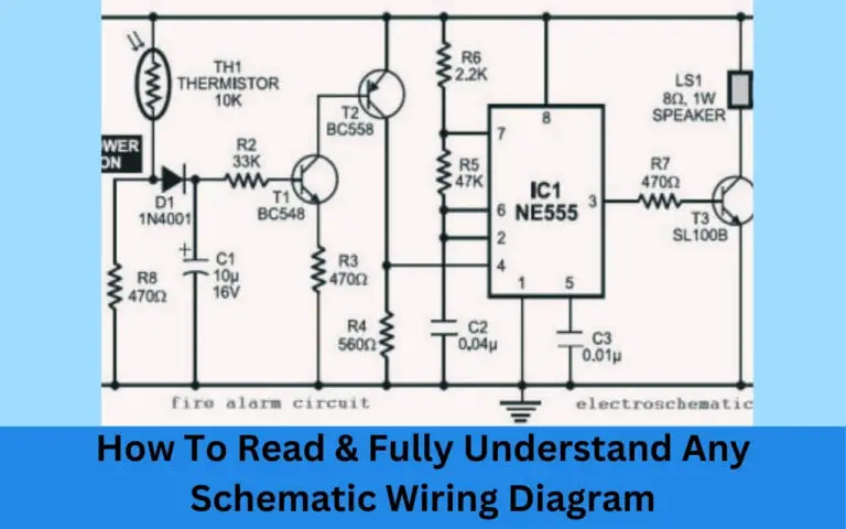
- Transistors – Semiconductor devices like transistors regulate current. Symbols differentiate between types of transistors.
These are just a handful of the many standard symbols utilized in wiring diagrams. As you work with more diagrams, you’ll quickly notice the consistent symbolic representations for electrical components which will help identify what different parts of a circuit represent.
How to Read a Wiring Diagram Step-By-Step?
Now that we understand what a wiring diagram represents and some of the standard symbols used, let’s go through a systematic approach to reading and understanding any wiring diagram.
Here is a step-by-step process to guide you through deciphering even complex wiring diagrams by focusing on one section at a time:
Step 1: Identify the Main System or Circuit
Start by identifying the major system represented by the wiring diagram you are looking at. Is this diagram showing a small low-voltage circuit, residential main electrical panel connections, or a motor control diagram?
Determining the overall focus provides some context even before tracing individual circuits. The system represented will give you hints about operating voltages expected and types of components likely to be included.
For example, knowing you are viewing a wiring diagram for a 24V industrial control loop provides critical context compared to residential 120/240V wiring prior to further diagnosis.
Step 2: Recognize Major Components
Before you dive into the wires and connections, take a high-level view of the major components included in the system. Identify transformers, motors, solenoid valves, motor starters, lighting ballasts, microprocessors, switches, and other significant components by their symbols.
Don’t yet worry about voltage values or terminal numbers. Simply identify the functional blocks. This gives you a parts list of components that wiring will be connecting when you trace circuits later.
Step 3: Note Operating Voltage Markings
As you scan a wiring diagram, take note of any voltage measurements labeled. Symbols representing test points for measurements may clarify voltage expectations for different points.
Typical voltage levels you may see noted include 24V, 120V, 208V, 230V, 460V, among other operating voltages a system may use. These labels will indicate what a circuit or component expects to receive when energized.
Step 4: Follow Circuit Pathways
Now you can begin tracing each individual “wire” shown in the diagram to understand all the interconnections. Follow the path noting each connection point between terminals of components. This reveals exactly how power flows when energized.
Mentally visualize or physically trace out how current begins from the source, powers equipment, returns through ground connections back the source. Tracking the current pathways familiarizes you with the complete functionality of the system.
Step 5: Watch For Potential Faults
Unfortunately, not all wiring diagrams represent safe or code-compliant installations. As you trace pathways, watch for any easily identifiable faults in the diagram:
- Missing ground connections
- Overloaded shared neutral lines
- Excessive daisy-chaining of power strips
- Safety disconnects wired incorrectly
While reading the diagram, be alert for these red flags to avoid recreating potentially hazardous circuit designs.
Step 6: Reference Against Physical Components
When available, compare the wiring diagram to the actual physical layout of components for the electrical system. This allows you to validate your tracing and understanding of the connections. Seeing how closely related the wiring diagram matches the real populated equipment increases confidence as you install additional circuits or diagnose issues.
With consistent practice tracing the pathways and connections in various diagrams, you will continually reinforce your ability to accurately interpret all the information contained in complex electrical schematics.
Real-World Wiring Diagram Examples
To apply these steps to deciphering wiring diagrams in various contexts, let’s walk through some real-world examples spanning simple low-voltage circuits to more intricate systems:
Wiring Diagram Example 1: Basic Light Switch
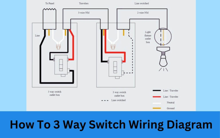
The simplest wiring diagram represents basic low-voltage, single-pole light switch wiring. This contains only an AC voltage source, single-pole switch component, light load, connections, and ground point.
Tracing out the diagram reveals how closing the manual switch loop allows hot current to flow from source, through the closed switch contacts over to the lamp load, then returns through ground back to transformer supply.
This basic example demonstrates the most essential wiring diagram components and connections possible to control a light.
Wiring Diagram Example 2: Home Electrical Panel
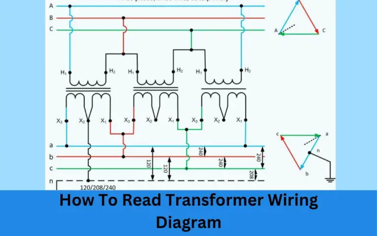
Scaling up, wiring diagrams are frequently used by licensed electricians for making residential and commercial electrical service installations. This electrical panel wiring diagram reveals the connections supplying a living space:
Examining this diagram shows the 120/240V feed from the commercial electrical grid transformer entering at the main panel service entrance. The integrated circuit breakers distribute power to lighting circuits, power outlets, appliances, air conditioners. Safety ground bars supplement grounding.
With many interconnected branch circuits, diagram analysis confirms appropriate wire gauge sizes used for expected current draws. Tracing circuits verifies grounded neutral returns exist avoiding code violations.
Wiring Diagram Example 3: Motor Control Starter
Industrial electricians rely extensively on wiring diagrams when installing and maintaining motors, pumps, compressors and other electric-driven equipment.
Unlike basic appliance plug-in diagrams, directly wired motor controls can involve intricate sequences of thermal overload heaters, sensors, pilot devices, control transformers, and motor starters.
Interpreting the diagram ensures technicians properly connect each relay, switch, and circuit. Verifying breaker lockout tag capability and emergency stop demonstrate additional essential safety aspects wired into the system.
Properly reading this diagram is crucial for electricians before deploying the reliable control of high-power machinery.
Wiring Diagram Example 4: Automotive Systems
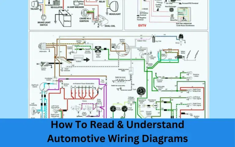
Even wiring diagrams of vehicles have standardized symbols, connector representations, wire routes and circuit tracings. Automotive mechanics and do-it-yourselfers use these frequently for repairs.
Typical voltage markings encountered in cars range from 13.5-14.5V as found in trucks. Diagrams assist troubleshooting electrical shorts, battery drains, malfunctioning external lights or internal switchgear problems. Wire repair harnesses depend on correctly identifying automotive wiring diagrams.
In each application, the examples demonstrate critical systems relying on correctly wired components according to the electrical drawings. Now having followed real scenarios, the techniques revealed in this guide equip you to better know how to read any wiring diagram.
Key Takeaways on Reading Wiring Diagrams
Being able to accurately read wiring diagrams takes practice but is an invaluable electrical skill allowing properly installed and maintained equipment. We covered quite a few key points in this guide including:
- Wiring diagrams visually show electrical component connections – They use standardized symbols, component representations, wiring lines, and text annotations to convey circuit details for installation and diagnostics.
- Several major benefits come from knowing how to read diagrams – Properly wired systems, avoiding hazards, informed troubleshooting, and assistance designing additional circuits.
- Common symbols represent components like switches, fuses, resistors – While variations occur, most electrical schematics follow conventions for symbols enabling universal understanding.
- Methodically follow a step-by-step process when presented with any new wiring diagram: Recognize major components, note voltage markings, trace pathways, watch for faults.
- Practical real-world examples – From basic light switches to vehicles, apply the diagram analysis process across countless electrical systems you may encounter.
With the right combination of symbol familiarity, connection tracing, and diagnoses for potential issues, wiring diagrams become powerful tools. Anyone working with electrical equipment should continually work to improve reading these “electrical blueprints”.
While wiring diagrams take time to master, remembering these tips will help boost comprehension. With regular practice, you will quickly gain the ability to review wiring diagrams for proper functionality. Stay safe and keep learning!

