How to Read & Understand Automotive Wiring Diagrams?
Have you ever opened the hood of your car and stared at the mess of wires and connectors not knowing what anything is or how it works? Or maybe you needed to troubleshoot an electrical problem but weren’t sure where to start when looking at the wiring diagram? Reading and understanding automotive wiring diagrams can look intimidating at first glance, but with a basic understanding of how the system works and some simple tips on what to look for, you’ll be interpreting those circuit diagrams in no time.
This in-depth guide will teach you everything you need to know about reading wiring diagrams so you can identify and diagnose electrical issues, carry out maintenance, and even take on full-on repair jobs on your own vehicle.
So what exactly is a wiring diagram and why is it so important for working on cars?
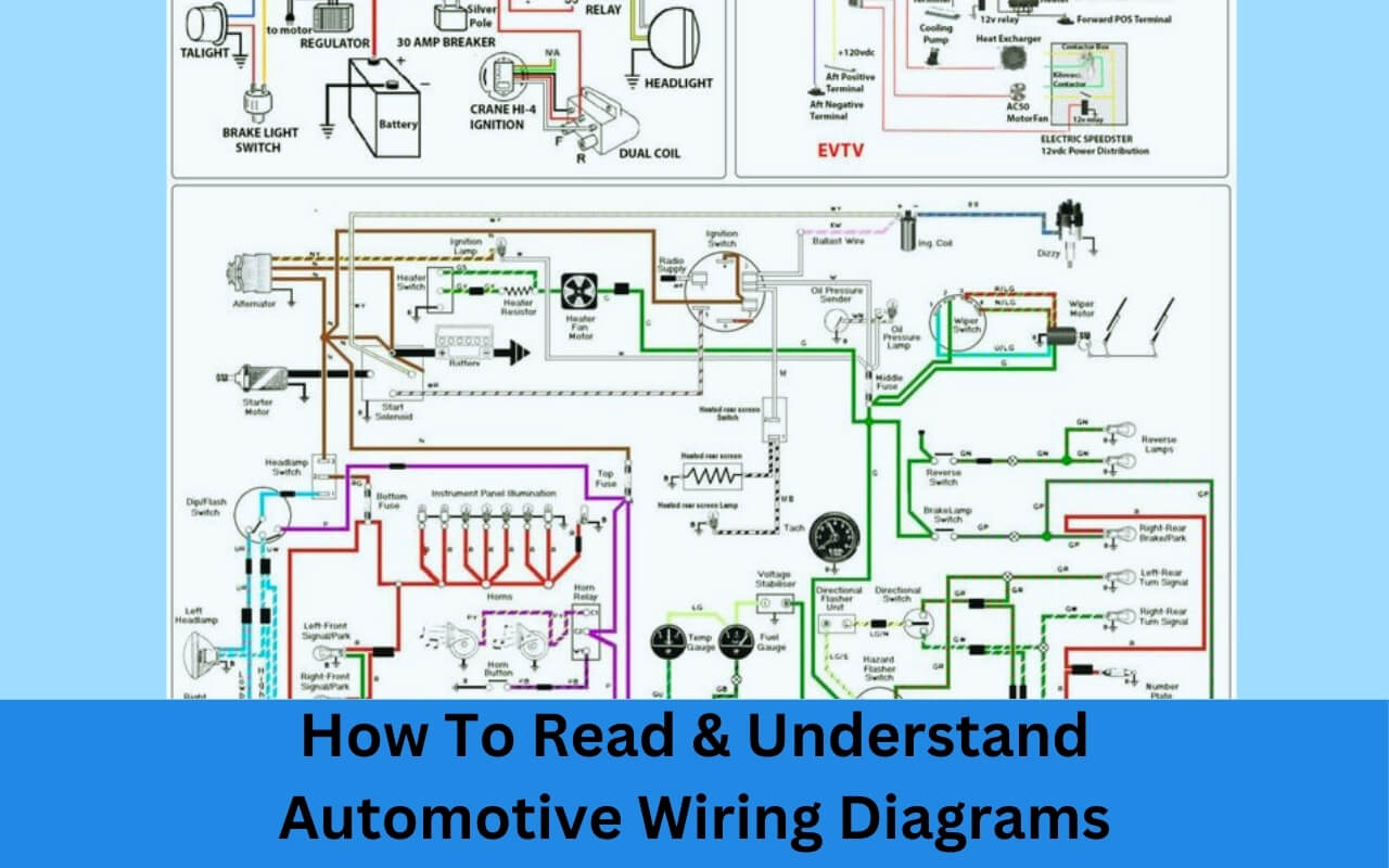
An automotive wiring diagram is a visual representation of the electrical circuits and connections found within a vehicle. It shows how various components like lights, sensors, and control units connect and operate by using symbols, color codes, relays, fuses, switches, and wires to define the circuit paths.
Wiring diagrams simplify complex electronic systems by using basic visuals to make them easier to read and understand for technicians and DIYers. Learning how to properly read these diagrams is the key that unlocks the ability to troubleshoot, repair, and customize a vehicle without needing to take it to the mechanic every time there’s an electrical gremlin.
We’ll cover everything you need to know about deciphering even the most complicated automotive wiring diagrams, including:
- Common symbols and what they represent
- Tracing the flow from power source to ground
- Identifying modules, connectors, splices
- Reading relay and fuse diagrams
- Where to find diagrams and schematics
So if you want to gain the confidence to finally tackle that nagging intermittent electrical issue with your headlights or are interested in installing aftermarket parts without constantly blown fuses, then this guide on understanding automotive wiring diagrams is perfect for getting you there!
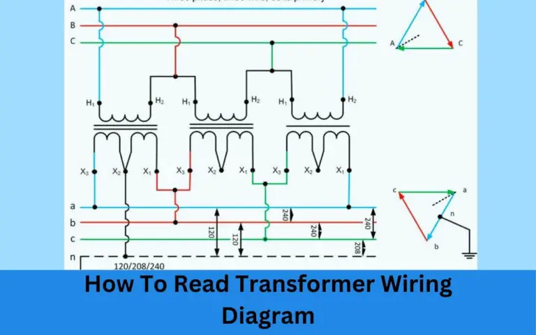
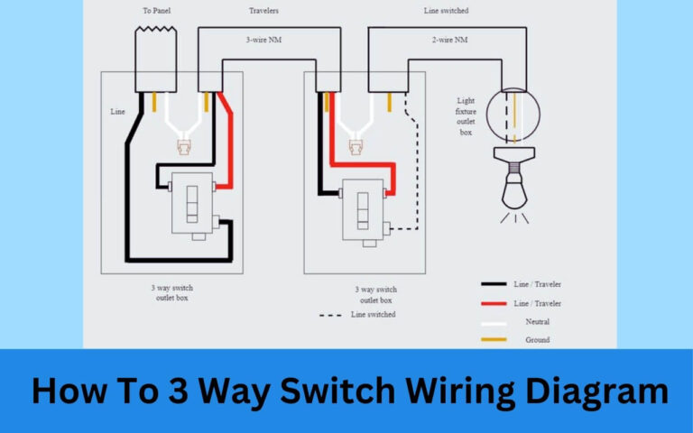
Automotive Wiring Diagrams
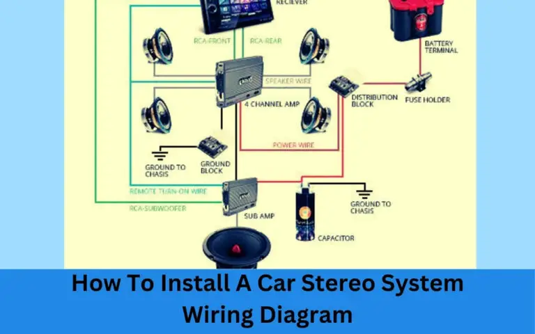
Diagram 1
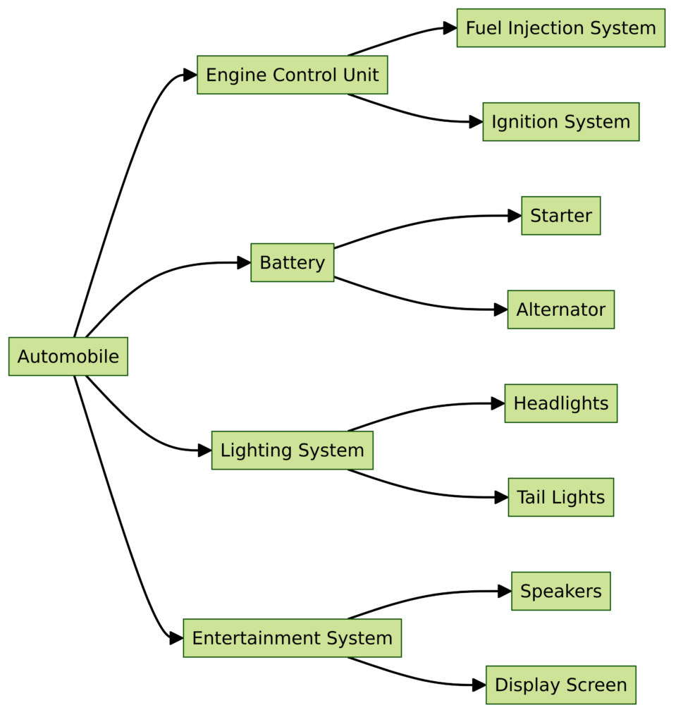
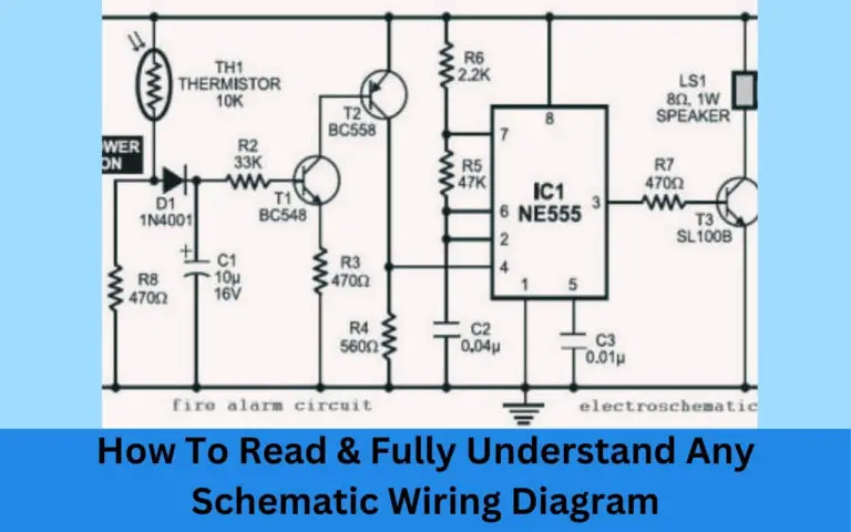
Diagram 2
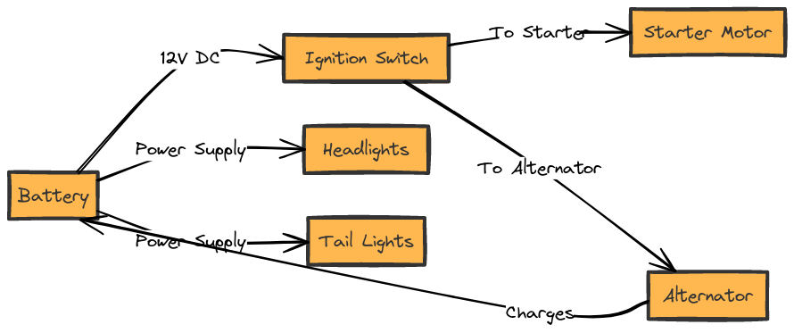
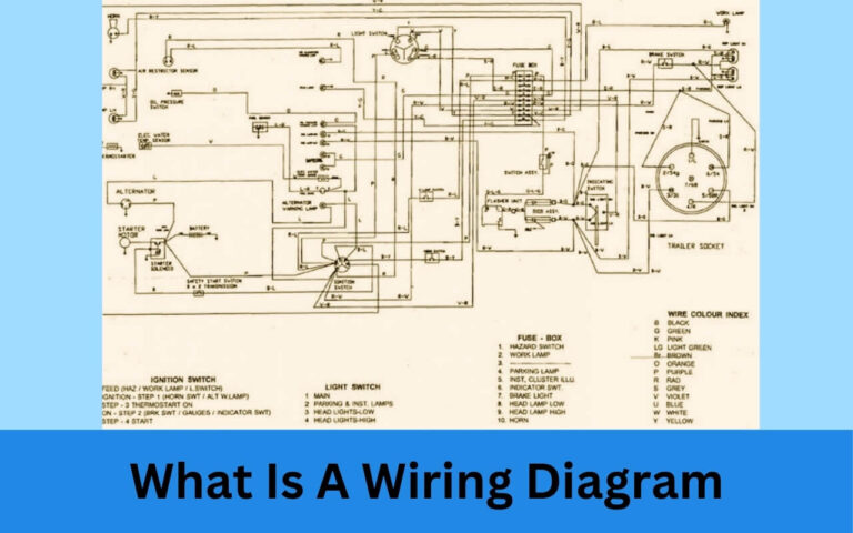
Diagram 3
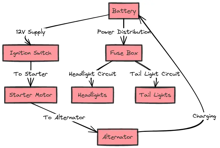
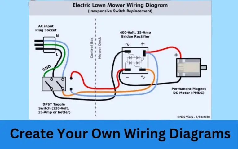
Diagram 4
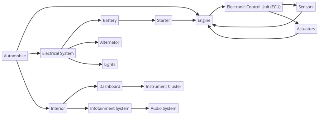
Diagram Symbols – The Language of Wires
The first step to reading wiring diagrams is understanding what all the symbols represent. The basic color and shape conventions used in diagrams represent the same components no matter what vehicle you’re working on.
Here are the main symbols you’ll encounter:
- Wires – Shown as lines connecting components. Color indicates function.
- Fuses – Represents overcurrent protection for a circuit.
- Relays – Act as remote controlled switches to operate high current circuits. Contain coils and sets of switch contacts.
- ECU/PCM – Engine/Powertrain Control Module – The brains of engine, transmission, and emissions systems.
- Resistors – Limit current flow. Represented by zigzag lines.
- Ground – Provides return path for current to flow. Shown as GND symbol.
Additionally, wiring diagrams use other standardized conventions to further identify what components do what and their properties:
- Wire colors – Red is power, black is ground, blue is data communication.
- Text labels – Clearly name the component a wire leads to.
- Dotted and solid lines – Indicate shielded or spliced wires.
- Terminal numbers – Define test points and connector pins.
So once you learn what the main symbols mean, you’ll start to see patterns emerge for certain types of circuits like lighting, ignition, sensors etc. It’s simply learning another language spoken not in words but through colorful symbols and lines!
Follow the Flow – Tracing Current in a Diagram
The key to properly reading wiring diagrams is to always follow the path from power source to ground. The power source provides voltage/current that allows components to turn on and activate. The ground path provides the return back to complete the loop.
Here is a quick procedure for navigating even the most complex automotive wiring diagram:
- Identify power source entry point (usually battery positive).
- Follow red power wire from source through various components.
- Note where branches lead to lights, relays, switches, and modules.
- Locate ground points tied to negative battery terminal.
- Verify each component path has a ground return.
Let’s walk through an example diagram for a basic headlight circuit:
- Power comes from positive battery terminal
- Primary wire goes to headlight switch
- Switch activates relay when on
- Relay connects to headlights
- Ground completes circuit through chassis
By visualizing the current flow across these components according to basic electrical principles, suddenly that confusing mess of colors and symbols makes sense!
Breaking Down Complex Diagrams
Many wiring diagrams can appear overwhelming at first glance due to seemingly disorganized sprawls of lines, symbols, and text. But most systems can be broken down into smaller sub-circuits and sections that can be tackled individually.
Here are some tips for decoding complex diagrams:
- Use page numbers and labels to identify sub-system sections.
- Check the legend to lookup codes and symbols.
- Find where power and ground enter section.
- Relate neighboring branches to that section.
- Cross reference with other system diagrams.
For example, by separating the ignition system, lighting, engine sensors, and body electronics into dedicated diagrams with clearly defined input power sources, what appeared indecipherable alone now becomes intelligible in context.
Real World Applications
Understanding the concepts is one thing but applying that knowledge to actual vehicle wiring diagrams is what will build true comprehension.
Here are just a few of the many systems you can learn to diagnose and repair by correctly interpreting automotive wiring diagrams:
Lighting Circuits
- Headlights
- Brake lights
- Turn signals
- Accessory/Dome lights
Ignition and Starting
- Ignition coil/distributor
- Spark plug wires
- Starter motor
- Battery positive/negative
Sensors and Control Modules
- MAF sensor
- O2 sensors
- TPS sensor
- Cam/crank sensors
- ECU and PCM
And many more essential and accessory systems found in any car!
Helpful Diagram Reading Tips
Here are some final tips to help get the most out of reading wiring diagrams:
- Start simple – Follow along basic light and switch circuits before jumping into complex engine systems.
- Use service manuals – Purchase diagram manuals specific to your vehicle for accurate schematics.
- Look up terms – Research components and principles you’re unfamiliar with.
- Study diagram examples – Compare notes with sample diagrams online to reinforce concepts.
- Test your understanding – Quiz yourself by identifying key components in any diagram.
- Apply your knowledge – Use diagrams to take on your own repairs without fear!
In Closing
Learning this new visual language opens up an entirely new world underneath the hood of your car. Instead of seeing a messy bird’s nest of colorful wires and strange components when you lift that hood, you can now appreciate the intricate world of carefully engineered electrical circuits powering everything in your vehicle.
So don’t let a simple wiring diagram intimidate you any longer! With this guide teaching you to decode even the most complex automotive schematics, you now have the confidence and knowledge to conquer any electrical gremlin standing between you and the open road. Go get em’ tiger!

