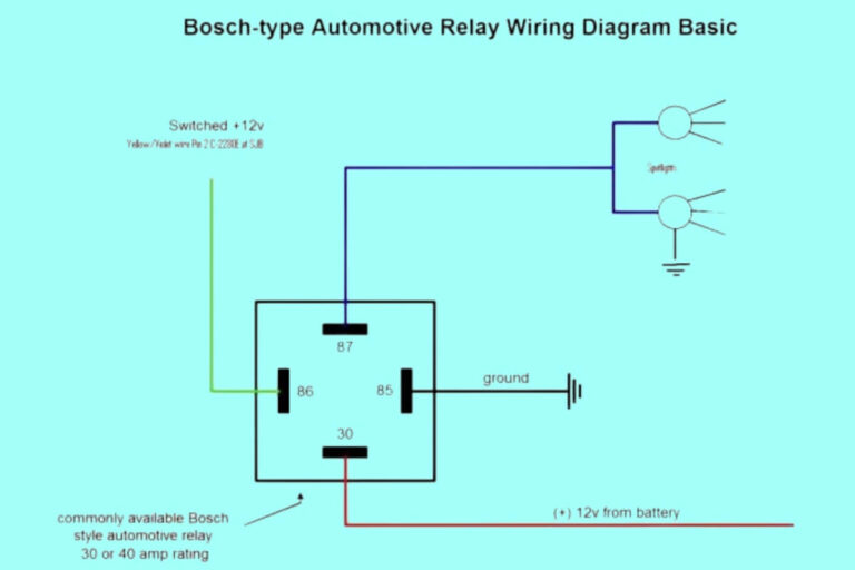
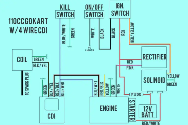
4 Pin Wiring Diagrams & Schematics
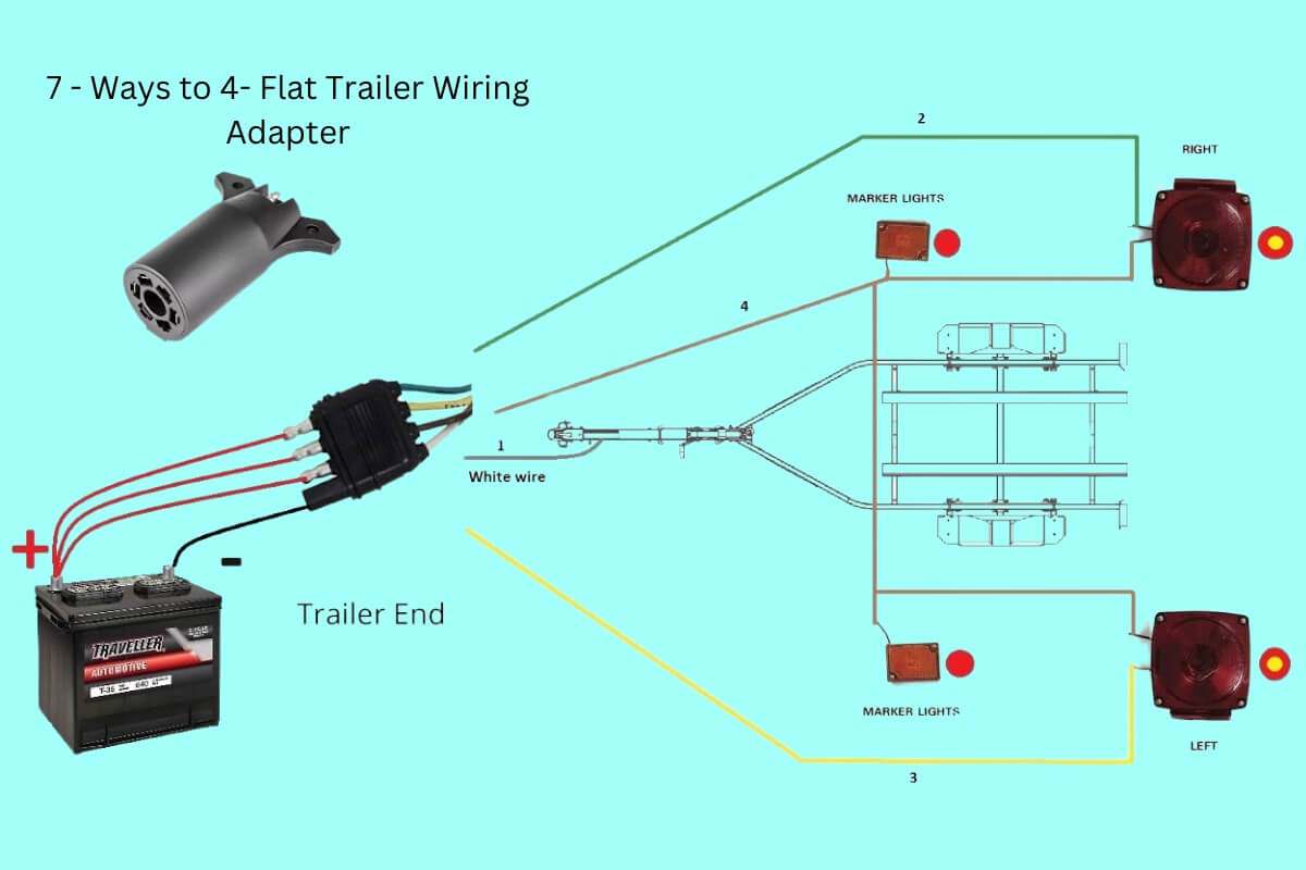
Traveling with a trailer can open up more options for transporting gear, equipment, animals, or other cargo to your destination. But being able to harness your trailer properly through correct wiring is key to making sure the lights and any electric brakes operate safely during your travels.
Many basic flatbed, enclosed, or utility trailers use a simple 4 pin trailer wiring connector to transmit power for the tail lights, brake lights, turn signals, and electric brake (if equipped). But if you’ve ever looked at a trailer wiring diagram and felt lost in a maze of colors and connectors, you’re not alone. Understanding the basic functions of each wire and how they connect from your tow vehicle to the trailer side can help ensure seamless electrical operation every time you hitch up.
So how do you make sense of 4 pin trailer wiring diagrams to safely harness even small single or double axle trailers? And what common mistakes should be avoided? Let’s find out!
4 Pin Wiring Diagrams
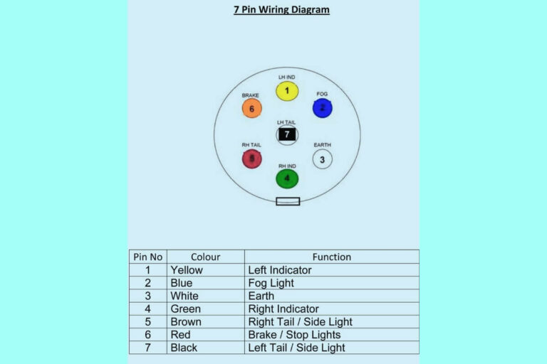
Diagram 1:
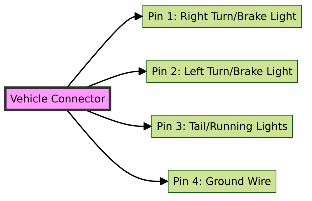
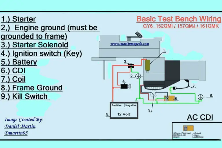
Diagram 2:
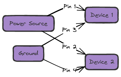
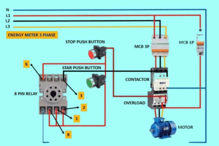
Diagram 3:
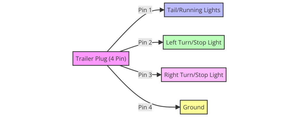
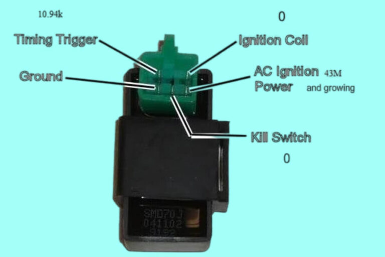
Diagram 4:

Do You Know the Purpose and Function of Each Wire in a 4 Pin Trailer Connector?
The basic function of a 4 pin trailer wiring connector is to transfer power for the lighting as well as brake signal from the tow vehicle to the trailer. The four wires also known as circuits each serve distinct purposes:
- Yellow Wire: Provides power to the left and right turn signals and brake lights
- Green Wire: Transmits power to the right tail light and brake light
- Brown Wire: Transfers power to the left tail light, brake light, and sometimes reverse lights
- White Wire: Connects to the ground wire
A dedicated ground wire is also part of the harness, usually white in color. The ground wire connects to the vehicle chassis and provides a return path back the electrical system for the lights to illuminate.
Understanding what each colored wire does as shown on the trailer wiring diagram, makes troubleshooting or testing much simpler. You know what to expect when you use a circuit tester on each one.
What Are the Key Components of a 4 Pin Trailer Wiring System?
In order to safely deliver power from your vehicle to the lighting on your trailer, a 4 pin system relies on several key components working seamlessly together:
The Wiring Harness and Connector
The wiring harness ties all the wires together, running from the vehicle connector to the lights on the trailer. The connector allows the transfer of power from the tow vehicle to the trailer harness.
Common types are flat four, flat five trailer connectors, or the round four pin connectors. Quality connectors protect against corrosion provide a solid connection through sturdy metal pins.
The Wires
The wire diameter (gauge) used matters greatly. Thinner wires can overload and burn out or blow fuses easily. Following trailer manufacturer recommendations or using 10-12 gauge wire for lights and electric brakes works well.
Using quality copper wiring with adequate thickness handles voltage drops over longer runs without power losses or burns outs. Marine grade tinned copper wiring offers incredible corrosion resistance.
Lights
Trailer light housings must stand up to weather exposure while protecting the bulbs or LED boards inside. Good sealant is essential around wires, lamps, and housing seams.
Submersible trail lights add an extra level of weather and water protection for the most extreme conditions. Work lights are also popular to see cargo areas better at night.
The Plug Termination Points
Where wires connect at the lights and the connector requires tight terminations. Any loose wires at these junction points can sputter, spark or send wrong signals back through the system.
Getting clean cuts on wiring free of frays then crimping properly ensures solid, lasting connections to the lights and connector plugs. Heat shrink tubing also improves plug durability.
What Are Some Common 4 Pin Trailer Wiring Diagram Configurations?
With a basic understanding of each wire’s purpose and how the components interconnect, next let’s explore some typical setups you’re likely to encounter:
Basic 4 Pin Trailer Wiring
The most common configuration is the basic wiring plan limited to just lights with no auxiliary circuits. This services tail lights, brake lights, left and right turn signals. No extra brake controller signal gets sent back through this basic system.
[Diagram showing basic wiring]
4 Pin Trailer Wiring With Additional Reverse Lights
Larger trailers often add reverse lights to the rear area for improved visibility when backing up. This requires tapping into the backup light circuit from the tow vehicle.
An additional blue wire ties to the vehicle’s reverse lights to activate the trailer reverse lamps in sync with the tow vehicle. This adds a level of customization in the wiring beyond just the basics.
[Diagram showing wiring with reverse lights]
Understanding Wire Colors on European 4 Pin Trailers
For those importing trailers from Europe, you may encounter slightly different wire color standards for the lighting. This varies from American trailer standards.
Here’s a breakdown on European standards:
- Yellow: Left Turn, Brake Light
- Red: Right Turn, Brake Light
- Brown: Taillight
- Blue: Fog light
So while the functions are similar, it’s the wire colors that change compared to US-standard trailers. Always reference the manual for imported trailer wiring diagrams.
Step-by-Step Guide to Reading 4 Pin Trailer Wiring Diagrams
Learning to navigate the meaning behind all those wires and symbols is critical before ever attempting to hook up your trailer connector. Let’s break down the process into clear bite-sized steps:
#1: Distinguish Vehicle Side vs Trailer Side
Trailer wiring diagrams label the vehicle and trailer sides distinctly. Usually a vertical line divides them clearly for easy identification. This matters hugely when wiring up a new plug or troubleshooting shorts.
Mixing up wires between truck and trailer can cause all types of problems. So distinguishing which side is which avoids headaches!
#2: Understand Wire Color Functions
Whether dealing with a custom diagram or universal guide, the wire color meanings do not deviate. Yellow is always left turn and brake lights, Green is right side, Brown is tail lights.
Memorizing their functions speed up properly matching vehicle and trailer wiring connections during harness work. Keep a basic diagram printout under the hood for easy reference.
#3: Locate the Ground Wire
The white ground wire placement often gets overlooked but is essential to completing each circuit. Power cannot return back to light the bulbs unless a dedicated ground finishes each loop.
Follow where this wire terminates at the frame near the connector. Make sure to connect any auxiliary grounds needed for brake controllers, etc to the same common point.
#4: Determine Which Lights Get Which Wires
With trailer wiring the right and left sides get split to their own wires. Green typically goes right, Brown left. Yellow crosses over to both brake light channels.
So noting which side gets which wires keeps things neat and avoids function overlaps or shorts. Especially important when adding additional reverse or external brake lights.
#5: Understand Master Control Circuits Like Brakes
With surge electric brakes and some hydraulic models, an emergency breakaway system engages the trailer brakes if separated from the vehicle. This detects whenever the trailer gets accidentally unhitched.
The wiring for electronic brake controls can tie into the central auxiliary pin on a standard 7-way as well. Just depends on your existing tow vehicle connector.
How to Wire a New 4 Pin Trailer Connector From Scratch?
Understanding the diagrams is essential prep work before physically wiring a new trailer connector plug. Once comfortable with the fundamentals, now let’s get hands-on attaching and routing wires:
Step 1: Select Proper 10-12 Gauge Wiring
Choose quality copper wiring approved for towing. Measure runs from the vehicle connector to light sources on the trailer, allowing 2-3 extra feet. Gather sufficient wiring for all trailer light circuits.
Step 2: Attach Connector Side Wires First
Solder seal or crimp on the vehicle side wires first directly to the connector plug. Redo any loose wires and tug test terminations to confirm tightness.
Step 3: Route Wiring to Lights
Run wires neatly along frame, securing with insulated metal clamps. Avoid rubbing locations and engine/exhaust heat. Apply protective loom wrap. Prepare light housing attachment points.
Step 4: Ground Trailer Frame Near Connector
Grounding the trailer properly to the metal frame bites away any electrical anomalies that can cause shorts. Use a star washer to penetrate paint and oxidization for robust metal contact at grounding block.
Step 5: Terminate Wires to Light Sources
Cut each wire lead precisely to avoid loose strands. Attach to rear running lights, brake lamps, turns signals, etc as dictated by wire color and function. Loops wires if bulbs are not installed allowing slack for later adjustments.
Step 6: Test Connections
With a helper hold a test light orcircuit tester to check if the correct bulbs illuminate when power gets sent down each wire from truck to trailer. Recheck grounds and terminals that don’t activate properly. Fix any issues before first road test.
Using a Circuit Tester to Confirm Proper 4 Pin Trailer Wiring
Verifying correct power flow through each wire can literally be done blindfolded (not while driving!) using a simple $10-15 circuit tester tool. Attached at any point along the wire length, these tools light up with power detected then signal wherever issues arise.
Here is a reliable process for diagnosing faults:
Step 1: Connect Trailer and Truck at Hitch
Making the electrical connection is required to allow a closed circuit so current can flow. No power equals no signal.
Step 2: Confirm Basic Light Functions First
Before touching tools, simply manually test basic brake, turn, and running lights first via the control switches. Get a helper to activate as you walk around.
Step 3: Attach Circuit Tester to Each Wire
Identify each wire if unlabeled by process of elimination. Inspect if the expected lights or brakes match the wire being diagnosed as the tester indicates closed vs open circuits.
Step 4: Toggle Switches While Testing
Have an assistant cycle through activating (brake signal, turn signal, reverse lights, etc) so you can trace what scenarios make the tester indicator behave erratically. Compare against expected outcomes per wiring guidelines.
Step 5: Recharge Battery Fully
A weak battery unable to hold full voltage can cause testers to deliver wonky readings that borderline pass but continue exhibiting problems down the road. Confirm reliable energy first before chasing ghosts!
While diagnosis will still require some sleuthing of specific problems areas, circuit testers help take a lot of guesswork out of interpreting trailer wiring diagrams during troubleshooting.
Common Mistakes to Avoid When Wiring 4 Pin Trailer Connectors
Without proper precautions, it’s easy to botch wiring trailer plugs. How can you be sure to get flawless performance each trip? Here are key pitfalls to avoid:
Mistake #1: Using Thin Utility Wire Instead of 12 Gauge Minimum
That spool of 14 gauge wire sitting your garage was meant for household 110v outlets, not hauling trailers! Thin wire heats drastically at highway speeds causing shorts. Spend a little more on quality 12+ gauge wire rated to high heat extremes.
Mistake #2: Forgetting To Ground Trailer Frame
While easy to skip especially on painted frames, missing this vital step opens up gremlins galore in all the lighting circuits without a return path to close each loop. Even small utility trailers need frame grounds back through the plug. Don’t pass go without one!
Mistake #3: Sloppy Connections Prone to Corrosion
Cheap splices without heat shrink, loose screw terminals, and cheap terminals will plague even simple 4 pin wiring. Solid mechanical and solder connections prevent resistance modulation from vibrations constantly altering voltage drops. Watertight wiring ends are also essential.
Mistake #4: Not Testing After Initial Installation
Assuming everything works right just by glancing at lights once is asking for headaches down the road, if not serious collisions hazards from lights dying later. Spend the time to methodically test each circuit completely using a tester tool as outlined above.
While not rocket science, neglecting basic practices inevitably spells disaster. Do it right the first time!
When Is It Time to Upgrade Trailer Wiring to a 7 Pin System?
While a basic 4 pin trailer wiring system meets the needs for small utility and cargo trailers, stepping up to larger 5th wheel campers or holding tanks introduces the need for additional high power towing capacities.
Upgrading to a 7 pin connector unlocks addition functionality:
- Separate turn and brake light channels
- Reverse lights for improved backing visibility
- 12v power line for trickle charging batteries
- Auxiliary power for accessories
Specifically for larger trailers, the extra brake signal wire enables trailer brake controllers to synchronize perfectly. Electronic brakes then match the deceleration rate of tow vehicle brakes for proportional stops.
The thicker gauge 7 pin wiring and extra pins cater to higher power demands. Just note that adapters are required to transition between 4 pin vehicles to 7 pin trailers unless the whole system gets upgraded.
Plan ahead when selecting a tow vehicle connector type to avoid constant adaptor headaches. Get the proper plug that matches your existing trailer.
Frequently Asked Questions About 4 Pin Trailer Wiring
Let’s recap answers to some of the most common questions about 4 pin trailer wiring setups:
Do the Wire Colors Vary Across Trailer Brands?
No, fortunately trailer manufacturers follow standard SAEE J1292 wiring guidelines. Green means right turn among all brands. The functions are consistent even if actual wire sheath color varies a shade or two.
Where Should I Mount the 4 Pin Connector?
Most receivers have a built-in 4 flat bracket. If adding a bracket, keep it high enough to avoid road grime but allow slack for tight turns. Ensure the connector does droop too low when unlocked.
Can I Power Electric Brakes on a 4 Pin Plug?
Technically no – when adapting a 4 pin from larger trailers down to 4 pin vehicle, brake lockout caps should be used to avoid overloading the basic system. For electric brakes, upgrade to 7 pin connector or an auxiliary brake controller instead.
What Gauge Wire Should I Use?
10-12 gauge wire suits most small 4 pin wiring applications. Step down to thinner 14 gauge only for very short runs under 10 feet. Over 15 feet, larger 8 gauge handles voltage drops for longer pulls. Excessive heat is the enemy so allow room to spare ampacity-wise.
How Do I Determine If Wires are Swapped?
Use a circuit tester to diagnose. When wires get crossed, odd behaviors occur like brakes illuminating as turn signals or vice versa. Methodically check each using an assistant to verify correct connections.
Why Am I Blowing Trailer Light Fuses?
Thinner gauge wire gets overloaded causing shorts from too many amps. Also corroded grounds cause entire circuits to get overpowered. Inspect grounds thoroughly and use maximum ratedtrailer wiringonly – never tinker with household wire grades.
Where Should I Install Grounds?
Find clean bare metal closest to the connector entry point on the trailer frame away from rust or paint for solid grounds. Also connect battery grounds directly to the same frame grounding point to avoid isolating the battery negative.
How Do I Crimp vs Solder Wires?
Soldering makes incredibly vibration-resistant connections but requires more skill. Crimp connections with proper heat shrink techniques also perform well. Avoid cheap crimp tools that smash connections vs piercing seamlessly into wires.
Why Test My 4 Pin Trailer Wiring?
Even quality work likely contains one or two errors difficult to spot from quick glance. Testing each light circuit using a helper while methodically confirming functionality takes only 5-10 minutes extra to save hours later chasing ghosts down backroads!
Glossary of Common Trailer Wiring Terms
Still trying to wrap your ahead around some key definitions? Here are clarifications on a few terms that confuse many first-timers:
- 7 Pin Connector: The larger capacity flat blade or round style connector adding more power-hungry circuits than a 4 pin. Commonly used on large trailers.
- Auxiliary Circuit: Any additional extra wired circuit beyond basic lights. Often used to add reverse lights, 12v power line for charge line, or electric brake signal wires.
- Breakaway Kit: Special brake kit that automatically activates trailer brakes if it becomes disconnected while driving. Prevents detached trailers from accumulating speed. Most electric brake trailers have one.
- Crimp: Flattens metal connector pieces tightly over stripped wire ends using specialized pliers. Forms water-resistant connection without soldering.
- Plug Terminal Area: The location where wire leads attach to the connector. Must withstand vibration, heat cycling and weather exposure without failing.
- Solder: Melting solder forms an incredibly vibration-resistant wire bond fused in a waterproof connection within plugs and light housings.
- Submersible Lights: Special heavy-duty LED lights built to withstand total submersion in water if boat trailers temporarily dip lights in lakes. Fully sealed.
Key Takeaways on 4 Pin Trailer Wiring
Getting those trailers lights blinking properly provides huge peace of mind delivering your cargo and vehicles safely at the campsite or job worksite reliably trip after trip.
In summary, remember these top pointers when working with basic 4 pin trailer wiring:
- Use only heavy 12+ gauge wires rated for towing to avoid shorts
- Ground trailer frames adequately – skip this vital step and suffer endless headaches!
- Adhere strictly to standard color wiring schemes for consistency across trailers
- Confirm solid metal-on-metal connections without relying solely on cheap splice caps
- Test all lights systematically before hitting the road using circuit testers to catch any missed issues
- Think safety first beyond just compliant lights – add extra seals, grounds straps, reinforced wiring looms, full testing, breakaway kits and other redundancy for trailer pieces that rattle relentlessly down highways for thousands of miles
We wish you many bright miles ahead on your trailer adventures! May all your wiring be snug as bugs in rugs. With quality components, safe routing practices, adherence to wiring standards, and proper grounds you’ll keep your cargo covered under working lights trip after trip.
Trailer wiring is an easy DIY project anyone can master themselves rather than outsourcing. Just take things step-by-step. Safety always takes priority with adequate wire gauge as the golden rule. Avoid shortcuts that will come back to haunt long hauls down the road.
Getting comfortable reading basic wiring schematics is a skill that pays back over and over. Understanding how individual wires crossover from your vehicle connector to power key functions onboard your trailer will grow your confidence handling both minor repairs and major upgrades.
Use the wiring fundamentals covered across connectors, routing, splicing techniques and testing procedures as a platform to launching more advanced trailer systems. Chases shorts vigilantly until found by process of elimination.
Admittedly diagnosing faults takes patience but prevents unsafe blowouts, loss of trailer braking or lighting failures in remote areas. Add protective loom wrap for longevity. Check all harness joints routinely before heading out.
With a solid understanding electrical principles unique to towing scenarios, you can handle whichever trailer wiring configuration gets thrown your way. Even massive 7 pin connectors become less intimidating.
So get out there and blink brightly under the sun, stars and moon with full confidence your cargo stays lit safely from mountains to valleys, campsite to home. May all your wiring connections shine brightly for years so come!

