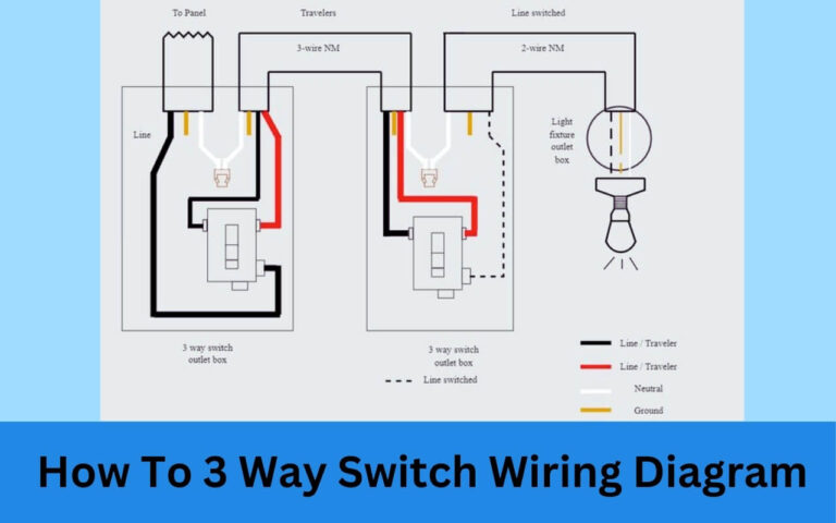
How to Read & Fully Understand Any Schematic Wiring Diagram?
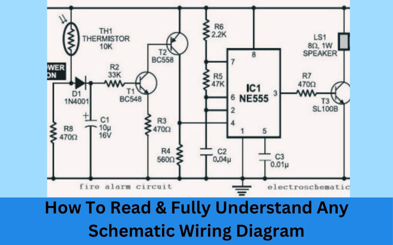
Have you ever opened up a wiring diagram or schematic and felt totally overwhelmed? Maybe you’re an electronics hobbyist looking to build a circuit from a diagram. Or an electrician trying to install or troubleshoot a complex electrical system.
What exactly is a schematic diagram, and why is it so intimidating to look at?
A wiring diagram or schematic uses symbols and lines to accurately represent complex electrical and electronic circuits. To the untrained eye, these diagrams look like a mess of lines and shapes placed almost randomly across the page.
But when you learn how to interpret what all those symbols and connections mean, reading a schematic becomes much easier. Mastering this skill allows you to work more efficiently on various electrical and electronics projects.
In this step-by-step guide you’ll learn:
- What a schematic diagram is
- The basic symbols used to represent components
- How to follow the connections in a circuit
- Tips for reading complex schematic diagrams
- Practical applications for understanding schematics
Follow along to demystify schematic drawings and start reading them like a pro!
What Exactly is a Schematic Diagram?
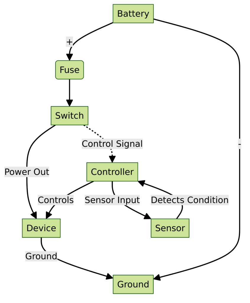
Before jumping into all the symbols and details on a schematic, it helps to understand exactly what a schematic diagram is intended to represent.
At its core, a schematic or wiring plan is a visual diagram showing how electronic components connect together to form a functional design or circuit. These drawings provide a logical way to visualize the interconnections and components themselves.
Some key things to know about schematics:
- Shows the logical connections and layout, not the physical positions of components
- Allows for design, building, testing and troubleshooting of circuits
- Used extensively in electronics, electrical systems, industrial controls, machinery, and more
For designers and engineers, developing schematics is an important first step in creating complex electronic devices and systems. For technicians, electricians and hobbyists, reading and understanding these diagrams is essential for installing, troubleshooting or modifying equipment.
A schematic presents the “big picture” view of complex circuits rather than the specifics of physical layouts.
Now let’s break down the common symbols and usage rules you’ll encounter on most schematic wiring diagrams.
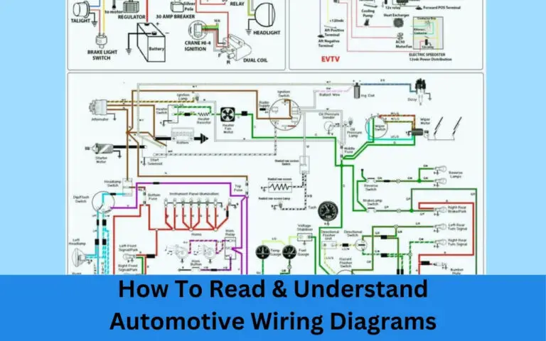
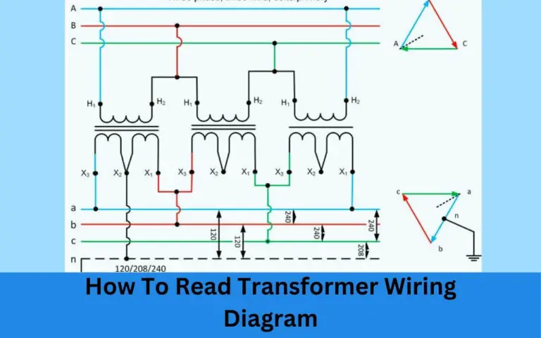
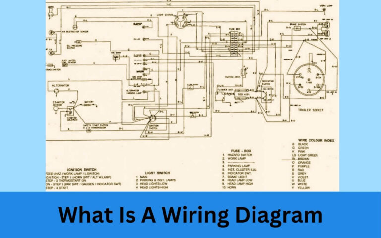
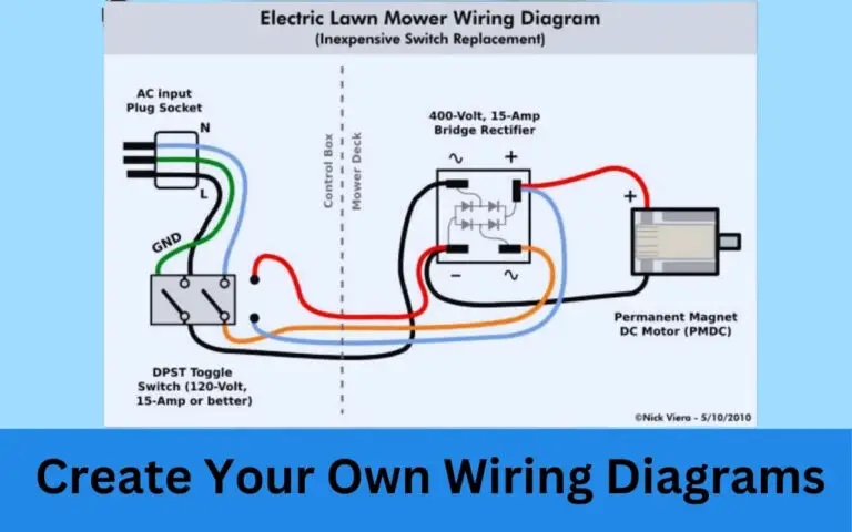
Schematic Wiring Diagrams
Diagram 1

Diagram 2
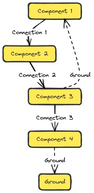
Diagram 3

Learning the Common Symbols
One reason newcomers find schematic diagrams so confusing is that seemingly arbitrary shapes are used to represent real electronic components.
However, while symbols may initially seem random, most follow simple rules to represent the functioning or properties of whatever component they depict. Here are some of the most common symbols encountered on schematic diagrams along with what they represent:
Wires
Wires are presented as solid lines used to interconnect other components. Sometimes these lines are different colors or thicknesses, which carry no meaning itself but help visualization of distinct connections.
Power Source
The power symbol shows where power enters the schematic diagram. The upper line indicates the positive voltage terminal while the lower one represents the common ground.
Ground
Schematics diagrams use the classic ground symbol to represent the ubiquitous common reference point for a circuit. This reference point, often called chassis ground, gives all other voltage measurements a baseline value of 0 volts.
Fuses
When fuses are included in a schematic diagram, they are always represented by their own symbol as opposed to just a wire connection. This allows for clearer understanding when diagnosing issues or identifying replaceable parts.
Switches
Various switch symbols represent momentary, maintained contact, SPST, SPDT and other types of switches or relays. Showing true switch states helps represent start-up, operating and shutdown conditions.
Resistors
Resistors restrict current flow. They are perhaps the most fundamental of electrical components. Resistor schematic symbols identify resistance values, power ratings and tolerance information.
Capacitors
Capacitors store and release electrical charge in circuits. The schematic symbol outlines its positive and negative pins. Non-polarized capacitors may use a basic rectangle while polarized ones add helpful polarity markings.
Inductors
Inductors use coiled wires to create magnetic fields that can store energy. Symbols represent whether an internal core aids field concentration. Values also define inductance level and tolerance.
Transistors
Transistors regulate current flows and act as signal amplifiers. Schematic symbols identify if a transistor is NPN or PNP and may include operating parameters to aid analysis.
Diodes
Diodes allow current to flow in only one direction, blocking reverse flows. Schematic diode symbols indicate the anode and cathode terminals. Zener diodes add an additional reverse-direction operating mode.
Integrated Circuits
Integrated circuits provide complex analog and digital functionality on a tiny chip. Generic outlines denote ICs as operational amplifiers, voltage regulators, drivers for logic gates and more. Unique codes identify individual chips.
Relays
Relays open or close contacts to control motors, high-power loads, external devices, and generate digital logic signals. Normally open and closed circuits are clearly marked along the relay body. Diodes snub back-EMF.
How to Follow Electrical Connections?
Being able to identify the individual components represented on a wiring diagram or schematic is only half the battle. Next you need to understand how all those components connect together into functioning circuits!
The first step is familiarizing yourself with the drawing itself. Schematic diagrams must be meticulous to allow accurate analysis and trouble-free operation of complex designs.
Here are some tips for orienting yourself to a new schematic the first time you reference it:
Identify Inputs and Outputs
Note where connections to external components exist on the diagram. Inputs bring power in and monitor signals from attached devices. Outputs connect internally generated signals to other equipment. Circle external connections for quick identification.
Follow Power and Ground Symbols
Every circuit needs power to operate and shared ground connections. Track where these enter the diagram and note how separate ground symbols tie together a common ground reference point.
Scan Signal Flow Left to Right
When following individual signal paths through a circuit, a left-to-right flow matches the way you read a schematic by default. Expect inputs on the left, signal processing in the middle, driving outputs on the far right.
Note Key Component Functions
Identify purposes of key components based on their symbols and connections. Group signals to conceptualize audio paths, motor drives, logic circuits, radio frequency (RF) flows, high voltage flows, etc.
Trace All Wires Related to Key Components
Pick individual resistors, transistors and ICs and highlight all associated connections to that component with colored pens or highlighters. This clarifies more complex internal sub-circuits.
By identifying the critical external connections, power circuits, major functions groups and tracing all wires attached to key components, you can simplify even the largest schematic into functional blocks.
You can now trace electrical flows across individual circuits. Follow some basic rules:
- Expect current to flow from positive to negative in power circuits
- Note inputs, signal operation blocks, and outputs in processing flows
- Watch for feedback loops and branching signal controls
- Pay special attention near textual callouts for labeled terminals
Use pens and highlighters liberally when first interpreting complex schematics on paper. Digital schematics also allow clicking individual wires and components to isolate their routing across the full diagram. With practice, you will learn how to read even dense schematic wiring diagrams fluidly while identifying key functions and operational parameters.
Reading Industrial and Commercial Grade Schematic Diagrams
With a comfort level following basic schematic wiring flows, you can now advance towards reading more complex diagrams used in industrial equipment and commercial electronics. Here are some tips:
Get Familiar with Ladder Diagrams
Ladder schematics bridge mechanical technical drawings used in manufacturing and electronics theory used in circuit board development. They integrate programmed operations with electrical control hardware.
Note Multi-Page Hierarchical Breakdowns
Large schematics divide overall systems into smaller sub-circuits detailed individually across many diagram pages. This supports a segmented yet interconnected design. Page numbers, revision details, dates and designer initials ensure proper version tracking.
Watch for Off-Page and External Connections
pages frame their defined sections while still integrating to the whole system through external connections. Lines with arrows, exited text callouts or component symbols drawn divided across page edges signify these off-page paths.
Reference Related System Drawings
Complex installations require electrical schematics, wiring diagrams, mechanical drawings, BOMs/component lists and assembly diagrams in companion. Cross-reference information across document types to access details only covered on specific sheets.
Always Note Redundant and Fail-Over Circuits
Mission critical real world systems incorporate extensive redundancies and monitored fail-over mechanisms to maximize uptime. Note duplicate power sources, active/standby component pairings, alarm circuits and system controllers.
While intimidating at first glance, remembering that all industrial schematics follow electrical theory fundamentals cuts complexity down to size. Break documents into functional blocks using callout labels and off-page connectors. Relate pieces across diagram pages based on common power, ground and signal paths.
Practical Applications for Reading and Understanding Schematic Diagrams
After covering schematic symbols, tracing flows and tackling complex multi-page diagrams, what can you actually do with this knowledge? Plenty – across electronics, electrical installations and monitoring industrial systems.
Building Circuits from Schematic Diagrams
With a schematic and a list of required components, hobbyists can order parts then populate a suitable PCB or breadboard to assemble a working circuit based entirely on the diagrammed design.
Diagnosing Issues from Schematic Documents
Technicians tracing erratic or dead signal flows on schematics find exactly where expected processing fails. Comparing with component datasheets rapidly pinpoints faulty parts needing replacement.
Performing Electrical Wiring Based on Schematics
Electricians rely on wiring diagram specifications when installing new appliances, distribution wiring, control panels and equipment control cabinets carrying high power levels.
Designing New Electronics Schematics and PCB Layouts
Engineers develop potential schematic diagrams focused on initial feasibility. Finalized drawings drive PCB layout and circuit optimization for performance, safety and compliance.
Reverse Engineering Circuits by Analyzing Components
With intricate electronics lacking schematics, skilled technicians map actual circuit construction. This allows cloning or improving outdated consumer electronics, appliances and industrial electronics.
Learning to read schematic diagrams helps modify, troubleshoot or install complex electrical and electronic projects. It aids working safely around high power voltages. This versatile skill scales from basic hobby builds to advanced industrial control systems and everything in between.
Tips for Learning How to Read Schematic Diagrams
Here are some final tips if learning to read schematic diagrams seems daunting:
Start with Simple Practice Circuits
Find basic schematics with less than 10 components and follow all power, ground and signaling wires. Check comprehension by examining or building the actual circuit.
Compare Diagrams to Real World Circuits
When maintaining equipment with existing schematics, cross-reference wiring between the diagram and actual construction. Clarify confusing connections by inspection on the physical circuit.
Practice Reading Increasingly Advanced Commercial Schematics
Download schematics for appliances, motor controllers, power supplies and electronic devices. Highlight all instances of common symbols. Guess at overall functionality before checking descriptive text.
Reference Multiple Tutorials and Quiz Guides
Many websites offer random schematic snippets along with interactive testing of symbols and circuit tracing. Test knowledge with topic specific quiz books offering answer keys to check progress.
Enlist an Electrical Mentor for Guidance
If struggling, reach out to an experienced electrician, PCB designer or electrical engineer. These experts best clarify details lost between textbook theory and real world weathered wire connections!
Conclusion – A Foundational Building Block for all Electrical Work
Learning to read even the most complex schematic wiring diagrams allows you to work confidently across endless electrical and electronics applications. Mastery separates true electrical experts from dabblers – granting you access to the core of all modern technological wizardry!
This introduction covered why schematics matter, common symbols, tracing flows, reading complex industrial diagrams and building real world skills. With this foundation (along with patience and practice) schematics become your superpower instead of a frustrating roadblock.
Now that you understand the graphical language of schematics, dive deeper into electrical theory and practical construction techniques. Master electrical waveforms, signal processing, sensor integration, safe installations, relevant codes and best practices across fields spanning industrial automation, robotics, automotive electronics, home IoT technology, commercial AV systems and far more.
When ready to show off new schematic diagram reading abilities, browse CircuitLab’s open project designs, kickstart a new hobby electronics breadboard prototype or dive into maintaining equipment at home or work. Document your expanding electrical journey below!

