Create Your Own Wiring Diagrams: Complete Starter Manual

Have you ever opened the back of a computer or peered inside a light fixture and confronted a confusing rat’s nest of wires and connections? Or maybe you’ve wanted to redesign the layout of your home’s electrical system but didn’t know where to start.
How exactly do you make sense of electrical spaghetti or map out an electrical project?
The answer is a wiring diagram. These specialized drawings use standardized symbols to document the components, connections, and flow of electricity.
In this in-depth guide, we’ll teach you everything you need to know to read, design, and get the most value from wiring diagrams. You’ll learn how they work, essential drafting skills, software tools to simplify the process, and examples for various applications.
Whether you’re an aspiring electrician, tinkerer, or just trying to operate that newfangled appliance, crafting your own wiring diagrams will enhance your understanding and empower your projects.
What Is a Wiring Diagram and Why Do You Need One?
Let’s start by defining some key terms:
- Wiring diagram: A simple diagram showing the physical layout of an electrical system or circuit and how wires are interconnected. Uses standardized symbols to represent components.
- Schematic diagram: Focuses on the logical function rather than physical layout. Symbols show components and connections but not exact wiring paths.
- Pictorial diagram: A detailed physical layout showing exact wire routing as it looks in real life. May have little symbolic representation.
Diagrams serve many critical purposes:
- Visually map out connections and layout for electrical construction and repair
- Provide instructions in appliance manuals and other documentation
- Understand circuit behavior and aid in diagnosing problems
- Design and test new systems more safely and effectively
They allow anyone to decode the abstract complexity of electrical systems with simple visual representations.
In short, a wiring diagram can save you from headaches and hazards. Keep reading to start mastering the art yourself!
How to Read and Understand a Wiring Diagram?
Being able to interpret wiring diagrams will make you better equipped to work with electricity and electronics. While they may look complicated at first glance, diagrams use fairly intuitive symbols and visual language once you grasp the basics.
Common Symbols
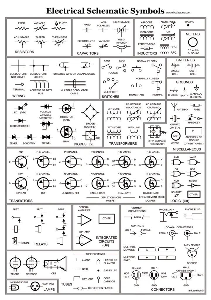
All diagrams use specialized shapes and icons to represent real components. While symbols differ slightly between industries, the examples below are common building blocks:

With just a glance, you can identify switches, resistors, capacitors, integrated circuits, and more. You can even deduce additional info like normally open or normally closed contacts.
Straight lines connect symbols to show wires and connections between components. Diagrams organize symbols spatially according to the real layout.
Visual Language
But diagrams show more than just individual components. Thicker lines often represent power sources with color coding like black for hot wires or green for ground wires. Arrows demonstrate the direction of current flow.
Dash lines indicate circuits that are connected but not necessarily physically adjacent in a project. Reading wiring diagrams takes practice but follows logical visual language.
What’s Not Shown
However, even good diagrams omit certain information. For example, they show how components connect, not the real routing of wires through walls and fixtures. 3D physical relationships and wire lengths are absent.
Diagrams also assume familiarity with basic electrical standards and physics principles to fully understand. But you can reference diagrams to trace connections and study components for many purposes.
Essential Tips for Drawing Clear Electrical Diagrams
While diagrams aim to clarify complexity, poorly-made ones can contribute to confusion. Follow these tips to create effective wiring representations:
- Use correct symbols: Consistently apply standard component symbols per industry and country guidelines.
- Organize layout logically: Arrange symbols spatially according to real physical layout when possible.
- Label everything: Identify parts with names, values like voltage/current, and polarity.
- Show connections clearly: Use neat lines between symbols to trace wiring paths.
- Communicate detail: Add dimensions, instructions, diagnostic data to facilitate construction and troubleshooting.
- Focus content: Determine scope and necessary info to share vs overcomplicating.
- Learn drafting skills: Use CAD programs, templates, and neat handwriting for clarity.
With practice, you’ll get better at distilling complexity to simple symbols, shapes, and lines. Great diagrams strike a balance between technical specs, visual clarity, and purpose.
Wiring Diagram Software Tools and Templates
While you can create diagrams manually, software makes editing and sharing wiring representations much easier. Programs like SmartDraw provide extensive libraries of symbols and templates to automate much of the process.
Benefits include:
- Drag-and-drop placement of symbols
- Connectors snap lines together
- Tools to customize appearance
- Libraries of thousands of components
- Templates for common wiring projects
- Automatic generation of diagrams based on model numbers
- Export options to embed or share as images
SmartDraw runs on desktops or mobile devices making it convenient to use wiring tools on the job. Its automatic layout tools even clean up connection lines!
Other popular options include Lucidchart for Macs or online use and AutoCAD Electrical for advanced professional applications.
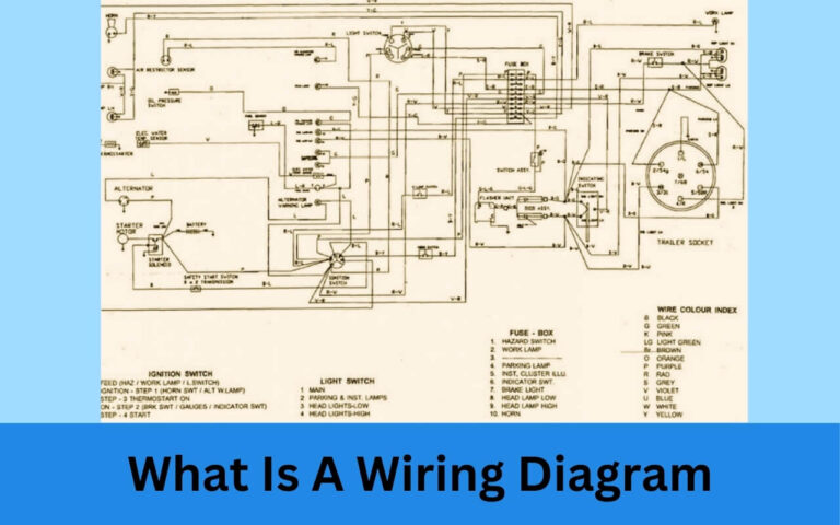
Or utilize free templates you can customize like this home wiring diagram:

The wealth of software tools empowers beginners and experts alike to create detailed, professional diagrams for any project!
Step-By-Step Guide to Designing Circuit Schematics
Understanding how to construct a wiring diagram makes electrical engineering more accessible. Let’s break down designing a basic schematic piece by piece:
1. Plan Key Components and Connections
First sketch symbols for core components like power sources, loads and switches based on project requirements. Map inputs, outputs and connections.
Consider technical constraints like voltage limits, current flows, and load capacities.
2. Choose Layout Strategy and Stylize
Arrange components cleanly for readability. Style wires, shapes, and symbols consistently. Number parts matching labels. Include project info like title and author.
3. Refine and Finalize Diagram
Confirm all necessary components are included. Double check labels and polarities match. Ensure symbols follow appropriate standards. Finalize lines and annotate further details.
Now test the schematic and make iterations as needed!
With an iterative approach, you can evolve basic diagrams into more polished and functional plans.
How to Create More Complex Wiring Layouts?
So far we’ve focused on basic single-page schematics. However, you may need to map more complicated wiring for homes, industrial sites, specialized equipment or circuit boards.
Here are some tips:
Multi-page diagrams
- Use page numbers and overview index pages showing parts integrated together.
- Include page specific titles/details with consistent styling for clarity
Physical layouts
- Show true 3D paths of wires, dimensions, and relationships
- Indicate distances for wire gauge calculations and building
- Can overlay or integrate into floorplans
Advanced software
- CAD programs enable easier large project design
- Include layers to hide complexity and generate views
- Specialized electrical BIM and diagramming tools
Alternative representations
- Hybrid approaches blend pictorial and schematic elements
- Photos/videos capture true as-is state
- Focus views on particular areas
Use these methods to troubleshoot and design electrical systems of any scale.
Applications and Examples of Electrical Diagrams
We’ve explored the foundations of wiring diagrams, but how do they apply in the real world? Here are a few examples:
Instruction manuals
Diagrams integrate into user guides for electronics, appliances and industrial equipment. They assist repairs, part identification and diagnostics.
Construction and repair
Electricians rely on accurate diagrams during building and renovations. They clarify circuit connections and fit electrical to structure.
Prototyping and testing
Engineers iteratively design, simulate, and test diagrams representing conceptual circuits before constructing them.
Distributed power generation
Complex facilities like data centers, ships and solar arrays need diagrams to manage scale. Icons can even dynamically represent status.
IoT and embedded systems
Compact diagrams integrate wiring with code and data. Alternate views convey software and hardware interconnectivity.
The use cases are endless! Diagrams enhance understanding across many fields and applications.
Common Electrical Symbols Cheat Sheet
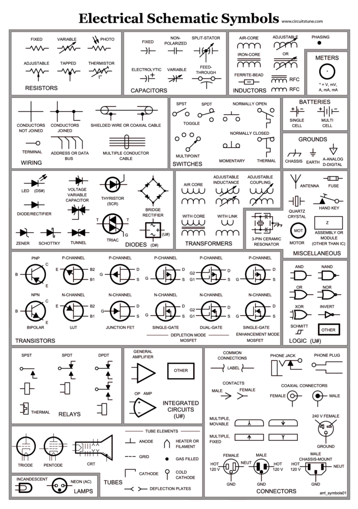
With hundreds of formal symbols, how do you know what to use? Print out this handy table for reference:

Notice standardized shapes grouped logically. Arrows indicate typical current or mechanical motion direction as applicable.
While not comprehensive, these examples illustrate common building blocks. Specialized fields have additional dictionaries. With practice, diagram syntax becomes second nature!
FAQ and Additional Resources
Here are answers to some frequently asked questions:
What’s the best software for wiring diagrams?
It depends on your use case. SmartDraw provides extensive libraries and productivity tools for common electricial diagrams. More advanced tools like AutoCAD Electrical offer additional capabilities but have steeper learning curves. Web apps suit basic schematics.
Can I automate diagram generation?
Yes, some tools integrate with databases and models to auto-populate diagrams. SmartDraw links to BIM software and can generate wiring diagrams from scratch by entering appliance model numbers. Scripting workflows produces iterations too.
How do I display my diagram digitally?
You can export diagram files to many static and dynamic formats. Embed SVG images in documents and websites that scale without losing quality. Use PDF to preserve professional formatting. Share live diagrams via cloud platforms.
Where can I access more symbol libraries?
Check out:
In Summary…
I hope this guide provided a solid introduction to designing, reading, and leveraging wiring diagrams! Here’s a quick recap:
- Diagrams visualize electrical connections with symbols to represent components
- Accurately mapping layouts and flows makes electricity less abstract
- Diagrams serve many functions across industries and applications
- Following best practices optimizes clarity for readers
- Modern tools help automate diagram creation and editing
With the skills from this post, you can more safely and confidently work with electricity. Diagrams break down complexity. You can now design a basic schematic, expand to more intricate systems, integrate diagrams into projects, and leverage them to diagnose or build circuits.
Our homes, appliances, vehicles and gadgets brim with hidden wiring keeping modern life functioning. While daunting at first, the electrical landscape becomes navigable with the mapmaking power of diagrams.
So grab some graph paper or fire up diagramming software. It’s time to illuminate electrical spaghetti!


