What Is A Wiring Diagram?
Understanding wiring diagrams is essential for anyone working with electrical systems. Whether you need to troubleshoot problems, install new equipment, or plan rewiring, wiring diagrams provide a simple way to visualize complex electrical connections.
But what exactly is a wiring diagram? A wiring diagram is a simplified conventional pictorial representation of an electrical circuit. It shows the physical layout and interconnections between electrical components using standardized symbols.
In this beginner’s guide, we’ll cover everything you need to know about wiring diagrams including:
- What a wiring diagram is
- Why they are used
- Different types of diagrams
- Standard symbols
- How to read diagrams
- Tips for creating your own
- Diagram examples
- Software tools
Let’s get started!
What is a Wiring Diagram?
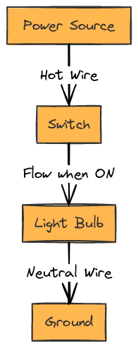
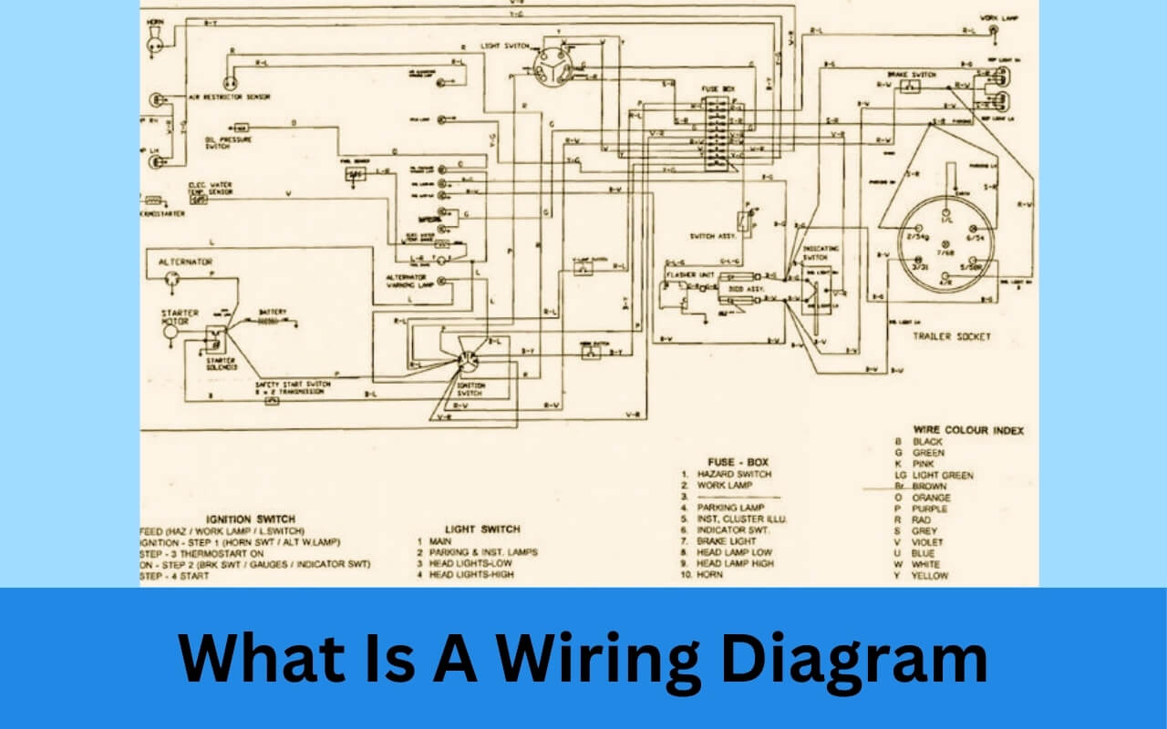
A wiring diagram shows the plan and function for an electrical circuit. It’s a simplified pictorial representation of the physical layout and interconnections between devices.
In other words, a wiring diagram uses simple images to show how electrical wires and components are connected together.
Wiring diagrams display how power flows through a circuit as well as the physical location of all components. This allows for easier troubleshooting when issues arise.
While a schematic diagram emphasizes simplicity and clarity of function, a wiring diagram shows more detail of the physical design.
Wiring diagrams are commonly used for:
- House wiring
- Control panels
- Lighting systems
- Alarm systems
- HVAC systems
- Motor control
Anything involving electricity and wires can likely benefit from a wiring diagram.
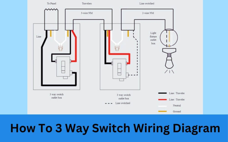
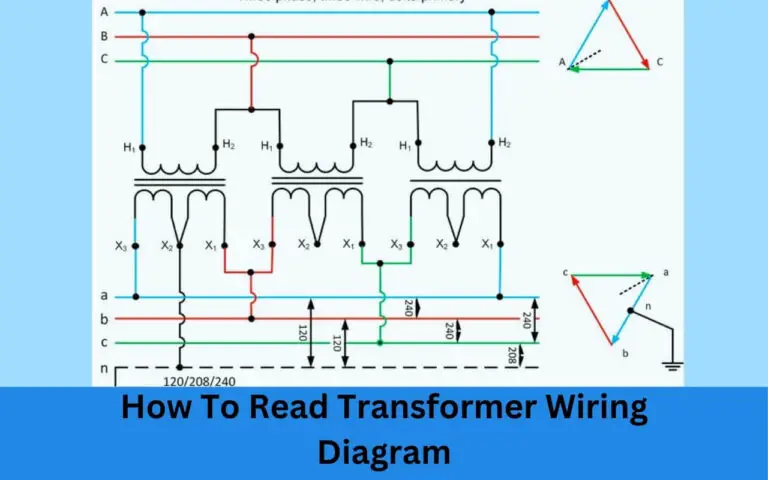
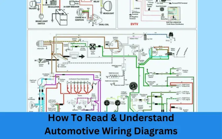
Wiring Diagrams

Example 2

Example 3
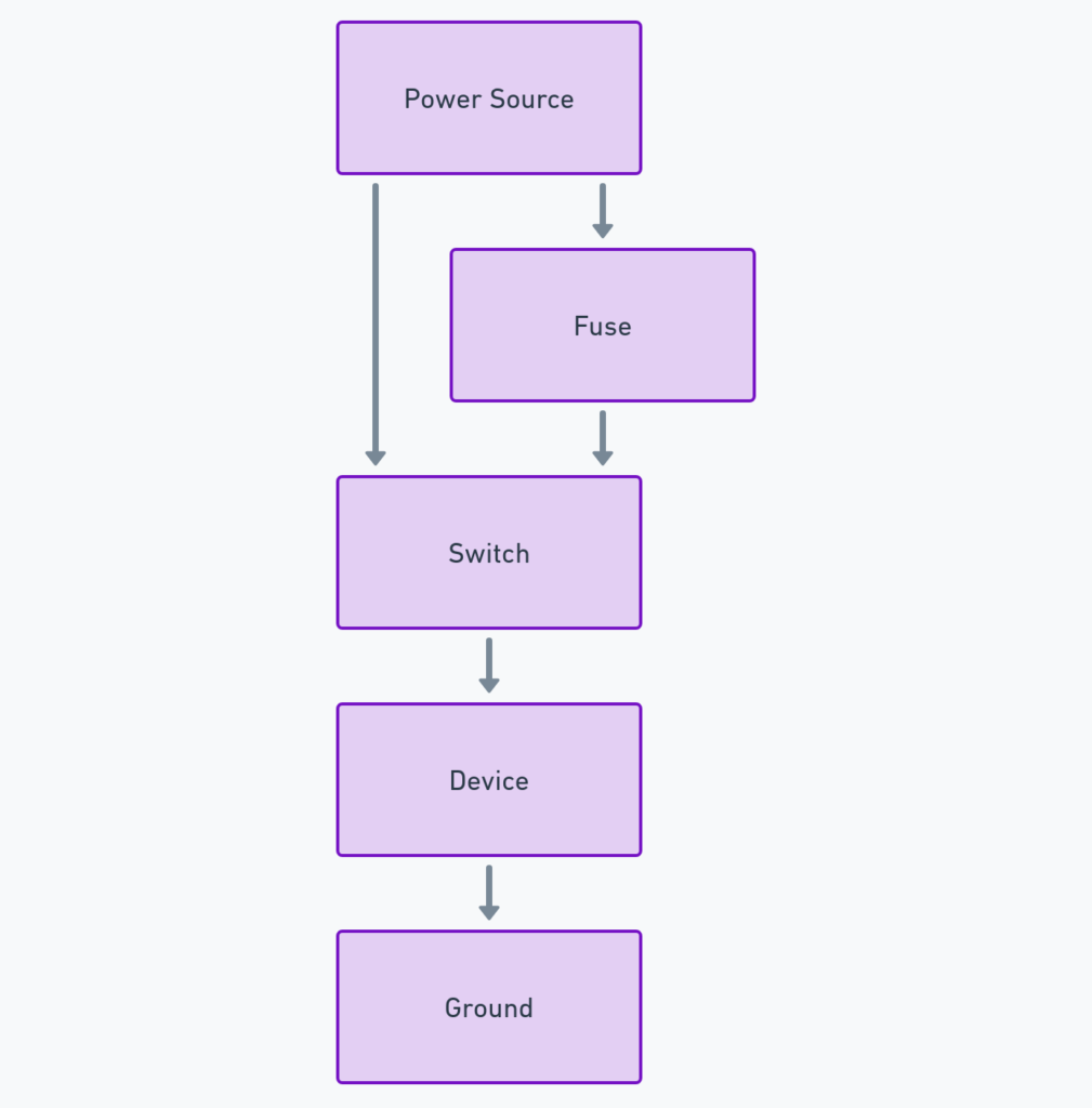
Why Use Wiring Diagrams?
There are many benefits to using wiring diagrams including:
Simplify Complex Systems
Electrical systems can be extremely complex with hundreds of wires and components. Wiring diagrams simplify electrical circuits by using basic images to represent components rather than showing every detail. This makes it easier to understand how systems work.
Troubleshooting Electrical Issues
When fuses blow or equipment fails, wiring diagrams facilitate troubleshooting. By seeing exactly how everything connects, problems can be isolated to specific wires, connections or components.
Install New Equipment/Wiring
Whether adding new lights, outlets or appliances, wiring diagrams show exactly how to integrate new wiring and components. Diagrams eliminate guesswork and mistakes during installation.
Understand Function of Circuits
Beyond just physical connections, wiring diagrams communicate the function and flow of circuits. This helps educate anyone working with electrical systems rather than just showing simplistic point-to-point connections.
Plan and Design New Systems
For new installations, wiring diagrams enable electrical plans to be drawn up to guide wiring and placement of outlets, switches, lights, control panels and more.
As you can see, wiring diagrams serve many critical purposes. Now let’s look at the various types of diagrams.
Types of Wiring Diagrams
There are a several major types of wiring diagrams including:
Pictorial Diagrams
Pictorial diagrams (sometimes called “picturesque”) show an accurate image of components and wire connections using basic images. Pictorials emphasize clarity of physical layout rather than focusing solely on electrical function. They act more like a photograph.
Schematic Diagrams
Schematic diagrams simplify circuits to their basic essentials. Using standardized symbols for components, schematic focus on showing electrical connections and functions rather than physical layouts.
Line Diagrams
Line diagrams are a middle-ground between pictorial and schematic diagrams. They show components and wires as simplified symbols but arrange them to resemble how they physically appear.
Ladder Diagrams
Ladder diagrams are specialized diagrams frequently used in industrial settings to illustrate control circuits. On a ladder diagram, wires and components stretch horizontally with components between two vertical supply wires, resembling a ladder.
As you can see, there are several flavors of wiring diagrams, each optimized depending on the intended use-case and user.
Key Components of any Wiring Diagram
While types may vary, most wiring diagrams have several key components including:
Standardized Symbols
Rather than drawing lifelike images of every component, wiring diagrams use abstract symbols to represent parts. For example, a simple switch symbol represents any real switch in the circuit. These standardized symbols simplify diagrams.
Wires
Wiring diagrams show wire connections between symbols. Often a “wire number” is noted to keep track of specific connections. Different colors or line styles (dashed, dotted, etc) can indicate different types or purposes of wires.
Power Source
The power source provides electricity to the circuit and is represented by provider supply symbols. Wires distribute this to components.
Electrical Load/Devices
The electrical load refers to whatever components or devices consume/use power provided in the circuit. These include outlets, lights, resistors, motors, appliances, etc. Symbols represent each load type.
Basically any wiring diagram needs standardized symbols, connecting wires, power source(s) and electrical loads to show a functioning circuit.
How to Read and Understand Wiring Diagrams
Learning how to interpret wiring diagrams is crucial for anyone working with electrical systems. While diagrams simplify complex circuits, they use standardized convention that require some learning.
Here are key tips for diagram literacy:
Recognize Common Symbols
The first step is understanding what different symbols represent. With experience, you begin intuitively understanding commonly used switch, outlet, lighting and other symbols. Always reference a symbol legend if provided.
Follow Flow of Current
Trace the wires in sequence from power sources to load devices and you’ll understand the flow of electricity through various components. Arrows often show directionality too.
Identify Inputs and Outputs
Determine what goes into each component and what exits. For example, a switch takes in power but only outputs electricity when flipped on allowing current to flow.
Ask Questions
Don’t just glance at a wiring diagram, actually parse how power flows through each element like you’re an electron travelling along! Figure out why connections route the way they do.
With some training, you can learn to effectively read wiring diagrams to understand electrical circuits. Now let’s explore creating your own.
Creating Your Own Wiring Diagram
Want to map electrical connections in your house, wire a new circuit, modify your car or document an electrical project? Creating your own wiring diagram ensures you fully understand the system while providing a valuable technical reference.
Follow these tips:
Use StandardizedSymbols
Use existing symbol conventions so anyone can easily interpret your wiring diagram. There are libraries of standardized electrical symbols to utilize.
Neatly Position Components
Place symbols and wires neatly allowing the diagram to be easily scanned. Group related elements together with power sources and destinations clearly defined.
Include All Connections
Don’t overlook any wires or connections to avoid confusion down the road. Show all components powered from each supply or you risk magic smoke down the road!
Label Everything
Use text liberally to label components, wire numbers, input and output pins etc. Assume whoever reviews your diagram lacks your intrinsic knowledge of the circuit.
Double Check Accuracy
Carefully inspect your finished diagram, validate all connections, ensure multiple reviewers check your work and run system tests before ever powering things on especially for high voltage circuits!
Real World Wiring Diagram Examples
Now that you understand the what, why and how of wiring diagrams, let’s look at some real examples:
House Wiring Diagram
This home wiring diagram shows the locations, wiring and types of lighting, switches, outlets and other components with power supplied from the utility:
Motor Starter Wiring Diagram
This diagram shows the control wiring for a three-phase motor:
Electrical Control Panel Diagram
Control panels route signals to various automated systems and equipment. This sample shows signal flows between controllers, sensors and activities:
These are just a few examples demonstrating the flexibility of wiring diagrams for documenting electrical circuits across various applications and industries.
Electrical Wiring Diagram Software Tools
Doing everything by hand can get laborious, especially for complex diagrams. Fortunately, there are various software tools to help quickly create wiring diagrams.
Top options include:
Edraw – User-friendly electrical diagramming suited for everyone from beginners to advanced users.
Visio – Very popular Microsoft Office tool for electrical engineering diagrams. Dozens of ready electrical component shapes and templates.
AutoCAD Electrical – Electrical toolset for advanced AutoCAD users with specialized electrical symbols and automation tools to simplify diagramming.
SmartDraw – Easy general purpose diagram software with lots of electrical symbol libraries for fast drawing.
Look for advanced editing capabilities, existing symbol libraries, custom templates and ability to link data to shapes when choosing software to help accelerate your electrical designing!
Key Takeaways about Wiring Diagrams:
We’ve covered quite a lot regarding wiring diagrams here. To recap:
Wiring Diagrams…
- Show electrical connections and functions for circuits
- Simplify complex systems using symbols
- Help troubleshoot faults
- Guide new wiring installations
- Multiple types of diagrams like schematics and pictorials
- Take effort to accurately build
- Are essential for anyone dealing with electrical
I hope this beginner’s guide to understanding and using wiring diagrams was helpful! Let me know if you have any other questions.

